
Efficient dilution method, including washing method for immunoassay

a technology of immunoassay and dilution method, applied in the field of biochemical assay, can solve the problems of low dilution factor of unbound antibodies, inefficient washing, increase in assay time and reagent usage, etc., and achieve the effect of efficient dilution

Active Publication Date: 2016-11-15
SHARP LIFE SCI EU LTD
View PDF11 Cites 3 Cited by
  • Summary
  • Abstract
  • Description
  • Claims
  • Application Information

AI Technical Summary

Benefits of technology

[0009]An aspect of the invention is a method of droplet manipulation to provide efficient dilution. In the case of an immunoassay, the method provides a means of efficient bead washing.
[0010]Such method may use control of droplet shape to control the area of contact between two droplets, which aids in control of the degree of fluid mixing between the two droplets.
[0011]In exemplary embodiments, such method may use control of droplet shape to minimize the point of contact between the two droplets, which aids in minimizing the degree of fluid mixing between the two droplets.
[0020]A simple method for providing highly efficient washing with high dilution factor, an important parameter in assay accuracy that avoids falsely elevated signals.
[0021]Reduces assay time by requiring fewer wash steps and reduces complexity, which is an important requirement for Point of Care applications.

Problems solved by technology

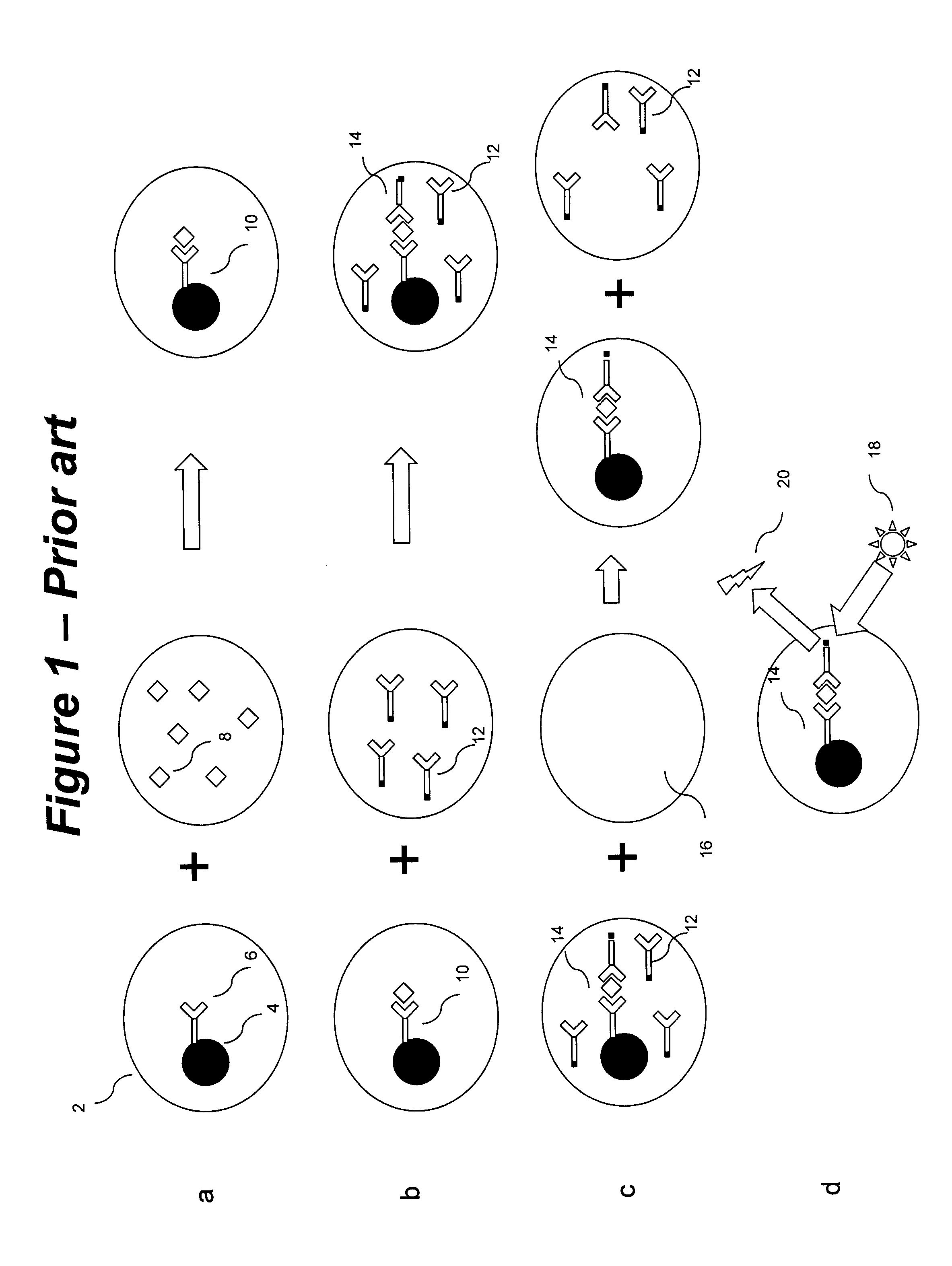
However, such an approach tends to only result in a low dilution factor of the unbound antibody due to the simple mixing of antibody droplet and buffer, which constitutes inefficient washing.
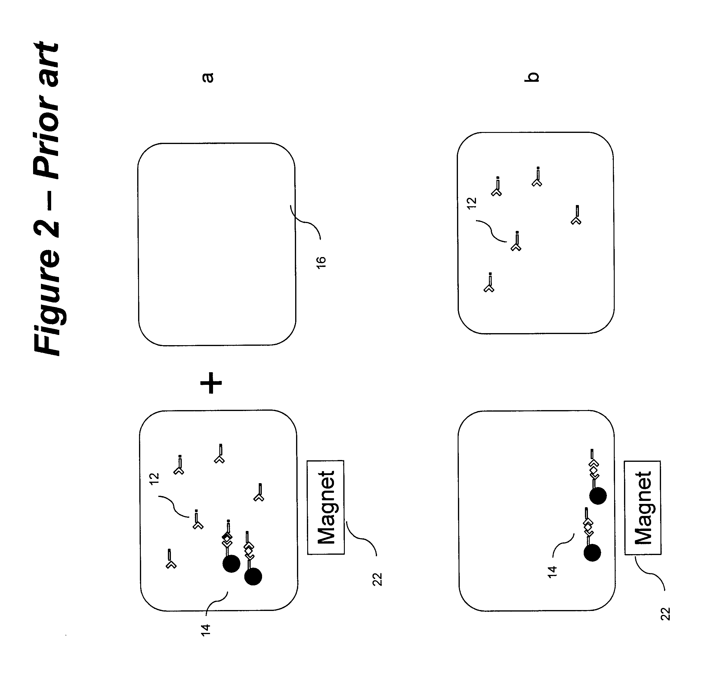
Therefore, the process of FIG. 2 requires many repeats of the washing cycle to achieve sufficient dilution, which increases assay time and reagent usage.
Pamula et al, however, does not describe how to achieve high efficiency washing.

Method used


Image

  • Efficient dilution method, including washing method for immunoassay
  • Efficient dilution method, including washing method for immunoassay
  • Efficient dilution method, including washing method for immunoassay

Examples


first embodiment

[0096]FIG. 3 shows the invention, illustrating an implementation of an exemplary washing method on an EWOD device. FIG. 3a shows a cross-sectional side view of such an EWOD device in which a droplet 2 is sandwiched between glass substrates 30 and 32 with a spacer 34 in between (the spacer being typically about 120 μm thick). There may be a filler oil 36 (e.g. dodecane) in the space between droplets. Further layers may be present on the inner surface of the glass substrates (not shown in FIG. 1) including for example electrodes (e.g. formed from Indium Tin Oxide), a dielectric layer (e.g. Silicon Nitride) and a hydrophobic layer (e.g. Polytetrafluoroethylene). The EWOD device may function so as to cause the droplets to move or adopt a particular shape.

[0097]The remainder of FIG. 3 shows a top view looking down on the device and illustrates the shape and relative position of droplets within the device. FIG. 3b shows a state comparable to the beginning of FIG. 1c. On the left is a firs...

third embodiment

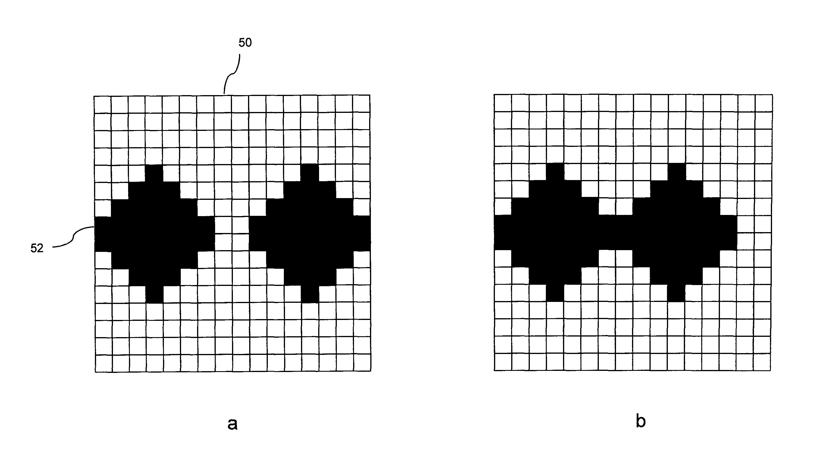
[0126]FIG. 9 shows the invention illustrating a means by which the droplet shapes previously described may be achieved using such an AM-EWOD system. FIG. 9a shows a grid illustrating part of such an array 50 of an AM-EWOD system. Elements that are colored black 52 represent those EWOD elements that are activated on the array, and the others remain non-activated. These two regions correspond to two of the substantially hexagonal droplets illustrated in the example FIG. 4b for example (third droplet not shown). The droplet shape is referred to as substantially hexagonal because a fluid droplet present in this region will adopt a broadly hexagonal shape as shown in FIG. 4. Due to surface tension of the droplet, however, it will not adopt exactly the same shape as the electrodes, i.e., the perimeter will not follow the exact “step-shaped” pattern but rather average to a smooth line more akin to the illustrative hexagons of FIG. 4. A second activation pattern is shown in FIG. 9b. When th...

fourth embodiment

[0127]FIG. 10 illustrates the invention showing an alternative means of achieving droplet shapes. Compared to FIG. 9, FIG. 10 represents a simplified array of electrodes in which a single electrode has a fixed shape which when activated commensurately produces the full shape of the drop required. Due to the reduced number and complexity of electrodes, direct wiring to each electrode is possible and thus appropriate voltages for EWOD activation are applied directly to each electrode. For example, a first shaping electrode 60 may have a fixed shape that commensurately shapes a first droplet when activated corresponding to the left hand droplet 2 of FIG. 4b, and track 66 provides connection to an external electrical supply. A second shaping electrode 62 may be provided and may have a fixed shape that commensurately shapes a second droplet when activated corresponding to the middle droplet 16a of FIG. 4b. Additional electrodes may be provided to shape additional droplets in comparable m...


PUM

PropertyMeasurementUnit
thickaaaaaaaaaa
wavelengthaaaaaaaaaa

Abstract

A method of droplet manipulation utilizing a droplet manipulation device includes activating elements of the device to bring a first droplet into proximity of a second droplet, controlling the elements of the device to alter the shape of at least one of the first and second droplets, and further controlling the elements of the device to move at least one of the first or second droplets until the droplets are in contact about an aggregate area. The elements are controlled in a manner so as to control the area of contact and the degree of mixing of the fluid between the first and second droplets. The method may be employed to move particles of a particulate suspension from the first droplet to the second droplet. The droplet manipulation device may be an electrowetting on dielectric (EWOD) device, which includes shaping electrodes activated to shape droplets, and a bridging electrode activated to join the droplets to transfer fluid between the shaped droplets.

Description

TECHNICAL FIELD[0001]The present invention relates to medical molecular diagnostics, and particularly relates to biochemical assays, for example antibody-based clinical assays (immunoassays). It also is particularly applicable to discrete droplet systems, for example, electrowetting on dielectric (EWOD) arrays.BACKGROUND ART[0002]The immunoassay is a well established technique for detecting targets in a biological sample (e.g. blood or urine) by employing an antibody specific to that target. Example targets may include cardiac markers such as troponin used to indicate the occurrence of a heart attack, or C-Reactive protein which is an indicator of infection. A common format is the “enzyme-linked immunosorbent assay” or “sandwich ELISA” assay, which requires such antibodies to be bound to a surface such as, for example, the wall of the reaction device or vessel. The use of polymer-coated beads as such a surface is known (e.g. Decker, GB2016687, published Sep. 26, 1979).[0003]FIG. 1 i...

Claims


Application Information

Patent Timeline
Patent Type & Authority Patents(United States)
IPC IPC(8): G01N27/447B01L3/00
CPCB01L3/502792B01L2300/0645B01L2400/043B01L2400/0427B01L3/502761B01L2200/0668
Inventor JACOBS, ADRIAN MARC SIMONHECTOR, JASON RODERICKMORGAN, HYWEL
Owner SHARP LIFE SCI EU LTD
Learn More