Combustion chamber wall

a combustion chamber and wall technology, applied in the field of combustion chamber walls, can solve the problems of large non-uniform temperature inside the combustion chamber, considerable thermal stress also occurring on the walls of the shell of the combustion chamber, etc., and achieve the effect of reducing the thermodynamic cycle efficiency of the turbomachine, avoiding non-uniform flow, and effective dilution of the combustion gas

Active Publication Date: 2018-12-18
SAFRAN HELICOPTER ENGINES
View PDF5 Cites 0 Cited by
  • Summary
  • Abstract
  • Description
  • Claims
  • Application Information

AI Technical Summary

Benefits of technology

[0009]An object of the present invention is to make temperature distribution within the combustion chamber more uniform, while increasing the thermodynamic cycle efficiency of the turbomachine. To do this, in at least one embodiment of an annular wall for a combustion chamber of a turbomachine of the invention, the plurality of cooling holes is also suitable for diluting the combustion gas resulting from said combustion by using the flow of air penetrating to the hot side of the wall through the cooling holes. Contrary to the prejudice of persons skilled in the art, it has been found that supplying air to such orifices of small diameter suffices not only to cool the walls of the combustion chamber, but also to achieve effective mixing of the combustion gas with the air delivered via these orifices of small diameter, thereby achieving effective dilution of the combustion gas.
[0010]In particular, in a second aspect of the invention, in such a combustion chamber, said cooling holes may present not less than 50% of a total surface area for passing air through the wall, and more specifically, at least 97% of a total surface area for passing air through the wall downstream from said at least one primary hole. It is thus possible to omit large quantities of orifices of large diameter for diluting the combustion gas, thus not only assisting in avoiding non-uniformities in the flow in the combustion chamber, but also making it easier to fabricate the dilution zone of the combustion chamber.
[0011]In a third aspect, in order to improve mixing between the combustion gas and the air delivered via the cooling holes, each hole of a plurality of said cooling holes is oriented along an axis that in projection on the wall presents an angle θ of not less than 45° relative to the direction of a central axis of the wall. In particular, said angle θ may lie in the range 85° to 95°. Thus, the air injected into the combustion chamber through the cooling holes follows a helical path, thereby lengthening its transit time in the combustion chamber and thickening the film of relatively cool air adjacent to the hot side of the wall, thus benefiting not only the cooling of the wall, but also the mixing of the combustion gas with the air in this thicker film.
[0012]In a fourth aspect, also for improving mixing of the combustion gas with the air introduced via the cooling holes, each hole of a plurality of said cooling holes is oriented along an axis presenting an angle β relative to the wall, the angle β being no greater than 45°, and preferably no greater than 30°. This ensures that the film of relatively cool air adjacent to the hot side of the wall is stable.
[0013]Nevertheless, in a fifth aspect, and also for the purpose of stabilizing the film of cool air, said angle β is not less than 15°, and preferably not less than 20°.
[0015]The present invention also provides a turbomachine, such as a gas turbine, a turbojet, a turboprop, or a turboshaft engine, in particular for an aviation application, the engine including a combustion chamber with at least one annular wall including a plurality of cooling holes, each having a diameter no greater than 1 mm in order to enable a second flow of air flowing on the cold side of the wall to penetrate to the hot side of the wall to cool the hot side of the wall, and also ensuring the dilution of the combustion gas resulting from said combustion by using the flow of air penetrating to the hot side of the wall through the cooling holes.

Problems solved by technology

This leads to considerable thermal stresses also occurring on the walls of the shell of the combustion chamber.
Nevertheless, that gives rise to other drawbacks.
In particular, those dilution air jets can give rise to large amounts of non-uniformity in the temperature inside the combustion chamber.
Unfortunately, for environmental reasons and for combustion efficiency reasons, it is important to ensure that temperature is distributed as uniformly as possible within the combustion chamber.

Method used


Image

  • Combustion chamber wall
  • Combustion chamber wall

Examples


Embodiment Construction

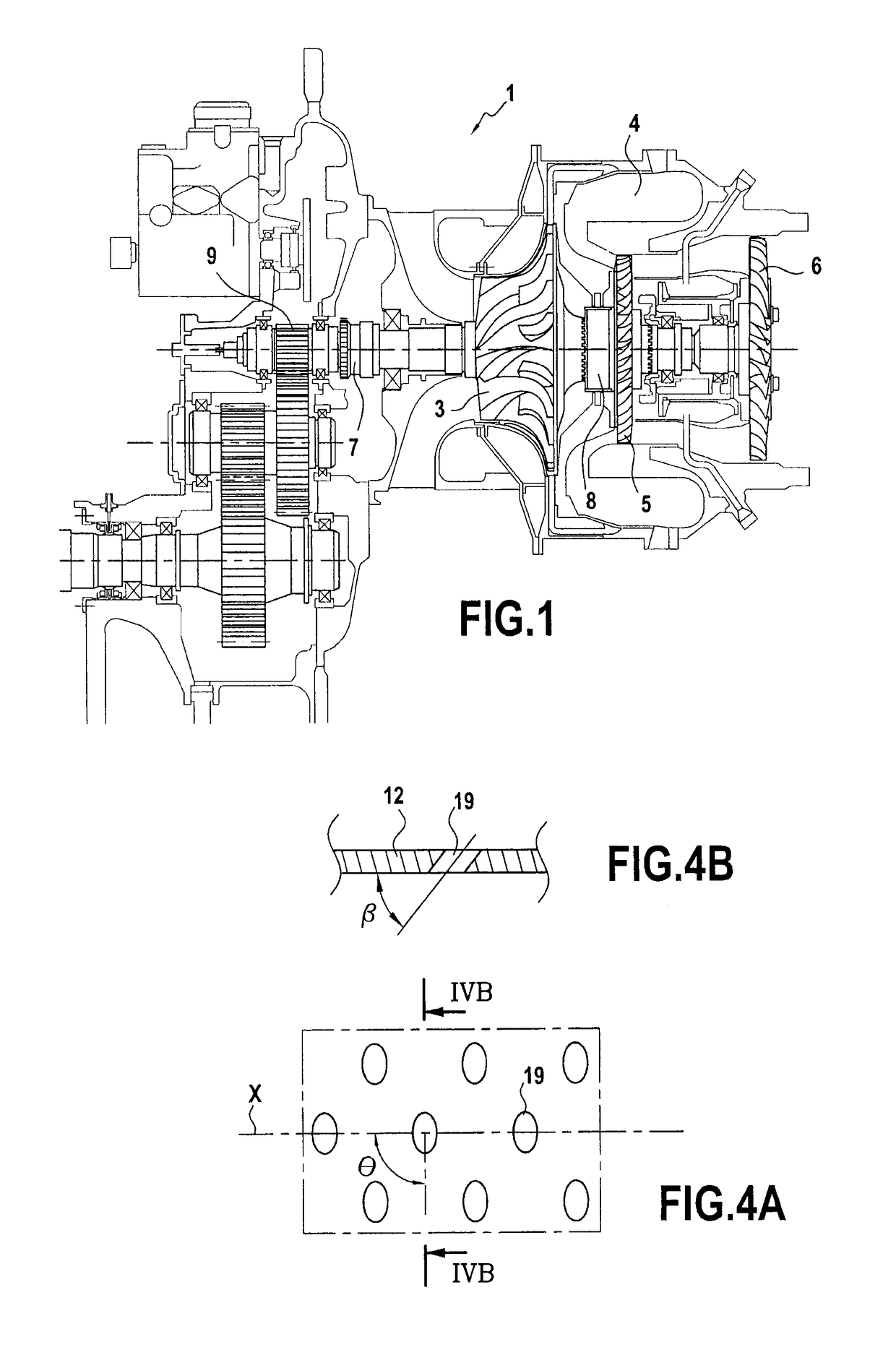
[0023]A turbomachine, and more particularly, a turboshaft engine 1, is shown diagrammatically by way of explanation in FIG. 1. In the flow direction of a working fluid, this engine 1 comprises: a centrifugal compressor 3; an annular combustion chamber 4; a first axial turbine 5; and a second axial turbine 6. In addition, the engine 1 also has a first rotary shaft 7 and a second rotary shaft 8 coaxial to the first rotary shaft 7.

[0024]The second rotary shaft 8 connects the centrifugal compressor 3 to the first axial turbine 5 so that the expansion of the working fluid in the first axial turbine 5 downstream from the combustion chamber 4 serves to drive the compressor 3 upstream from the combustion chamber 4. The first rotary shaft 7 connects the second axial turbine 6 to a power take-off 9 located downstream and / or upstream from the engine, in such a manner that the subsequent expansion of the working fluid in the second axial turbine 6 downstream from the first axial turbine 5 serve...


PUM


Abstract

An annular wall for a combustion chamber of a turbomachine. The wall presents a hot side and a cold side and includes at least one primary hole for enabling a first flow of air flowing on the cold side of the wall to penetrate to the hot side of the wall to feed combustion of fuel inside the combustion chamber, and together with a plurality of cooling holes, each having a diameter no greater than 1 mm, to enable a second flow of air flowing on the cold side of the wall to penetrate to the hot side of the wall to cool the hot side of the wall. The plurality of cooling holes can also dilute combustion gas resulting from the combustion by using the flow of air penetrating to the hot side of the wall through the cooling holes.

Description

BACKGROUND OF THE INVENTION[0001]The present invention relates to the field of combustion chambers for turbomachines, and in particular to the annular walls of turbomachine combustion chambers, which walls have a cold side and a hot side.[0002]The term “turbomachine” is used in the present context to mean a machine that converts heat energy of a working fluid into mechanical energy by said working fluid expanding in a turbine. In the description below, the terms “upstream” and “downstream” are defined relative to the normal flow direction of the working fluid through the turbomachine.[0003]In particular, the present invention relates to so-called “internal combustion” turbomachines in which the working fluid of the turbine includes at least some of the products of the combustion that has delivered this heat energy to the working fluid. Such turbomachines include in particular gas turbines, turbojets, turboprops, and turboshaft engines. Typically, such internal combustion turbomachin...

Claims


Application Information

Patent Timeline
Patent Type & Authority Patents(United States)
IPC IPC(8): F23R3/00F23R3/06F23R3/52
CPCF23R3/002F23R3/06F23R3/52Y02T50/675F23R2900/03041F23R2900/03042Y02T50/60
Inventor SAVARY, NICOLASBERAT, CLAUDEGRIENCHE, GUYBERTEAU, PATRICKVERDIER, HUBERT PASCAL
Owner SAFRAN HELICOPTER ENGINES
Why Eureka
Try Eureka