
System and method for characterizing ions using a superconducting transmission line detector

a transmission line detector and superconducting technology, applied in the field of particle detection, can solve the problems of maximum event rate, high detection efficiency, kinetic energy resolution, etc., and achieve the effect of extending the detection area, high efficiency and sensitivity, and not excessively long recovery tim

Active Publication Date: 2016-11-08
WISCONSIN ALUMNI RES FOUND
View PDF12 Cites 3 Cited by
  • Summary
  • Abstract
  • Description
  • Claims
  • Application Information

AI Technical Summary

Benefits of technology

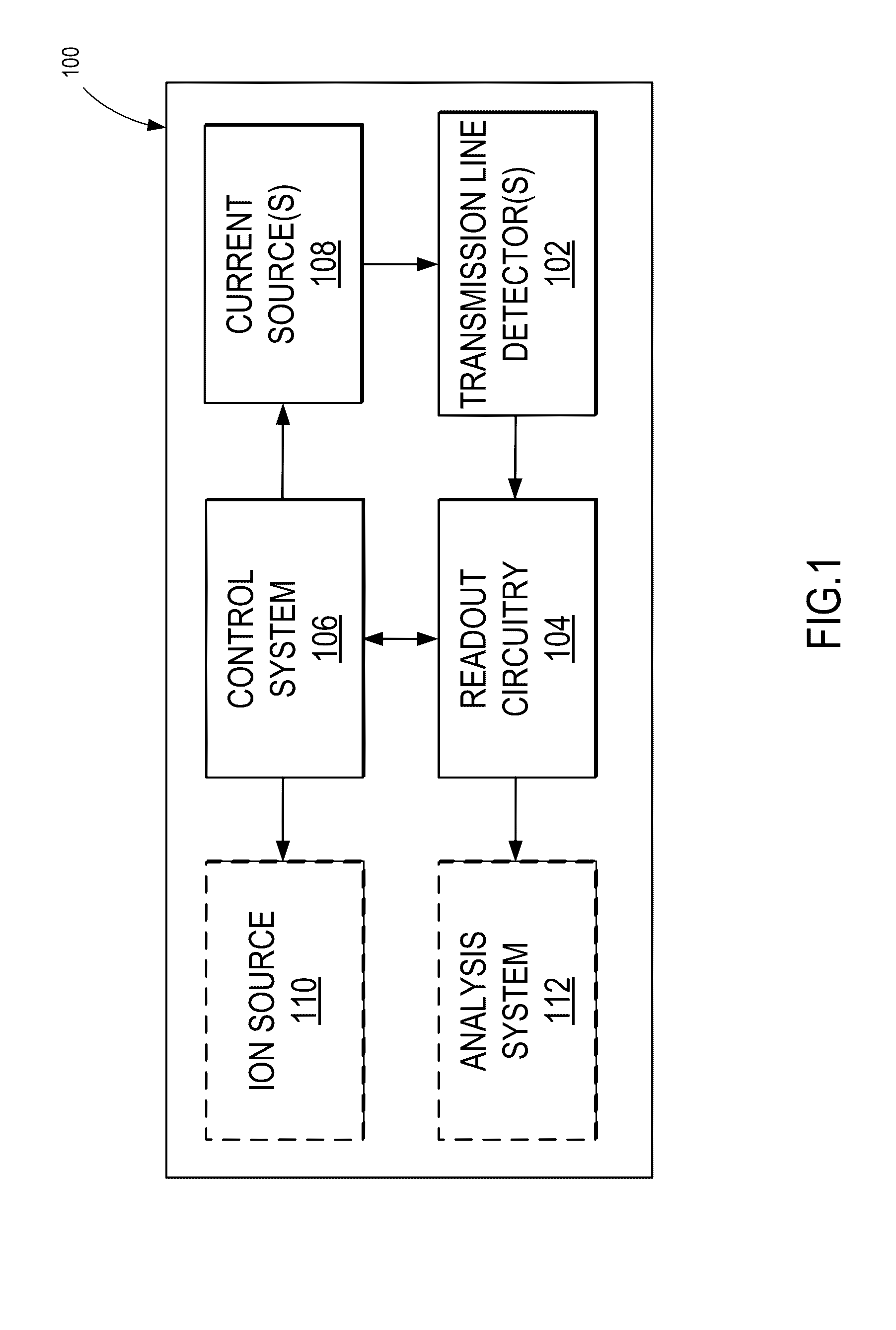
The present invention describes a system and method for detecting charged particles using superconducting circuits. The system includes a delay line detector that can provide positional and kinetic energy information for impact events. The detector is designed using extended superconducting transmission lines, which allows for efficient and sensitive detection without long recovery times. The features of this invention can be used in various applications, such as atom probe systems and time-of-flight spectroscopy systems, to improve accuracy and reliability. The delay line detector can distinguish between singly- and douly-ionized species with the same charge-to-mass ratio and time-of-flight.

Problems solved by technology

APT has particularly demanding requirements for the detectors.
The main weaknesses that need to be addressed include detection efficiency, kinetic energy resolution, multi-hit discernment, and maximum event rate.

Method used


Image

  • System and method for characterizing ions using a superconducting transmission line detector
  • System and method for characterizing ions using a superconducting transmission line detector
  • System and method for characterizing ions using a superconducting transmission line detector

Examples


Embodiment Construction

[0022]The present disclosure describes an approach for detecting and characterizing incident ions, using detectors capable of providing positional information and kinetic energy discrimination that overcomes deficiencies of previous technologies. In some aspects, novel superconducting delay line detectors are provided, which utilize substantially extended superconducting transmission lines for detecting ion impact events, in contrast to previously utilized superconducting high-kinetic-inductance nanowires or normal conducting delay lines. As will be appreciated from descriptions below, among other advantages, such superconducting delay line detectors make it possible to scale to any desired active area, and achieve position resolution. For instance, due to the fact that transmission lines have a real, frequency independent impedance, which is determined by the inductance and capacitance per unit length, the dead time of the detector no longer scales with the length. Furthermore, whe...


PUM


Abstract

A system and method for characterizing incident ions are provided. The method includes positioning a transmission line detector to receive incident ions, the transmission line detector comprising a superconducting meandering wire defining a detection area for incident ions, and applying a bias current to the transmission line detector. The method also includes detecting a first signal produced in the transmission line detector due to an ion impacting the detection area, and detecting a second signal produced in the transmission line detector due to the ion impacting the detection area. The method further includes analyzing the first signal and the second signal to characterize the ion. In some aspects, the method further includes identifying a delay between the first signal and the second signal to determine, using the identified delay, a location of the ion on the detection area.

Description

BACKGROUND OF THE INVENTION[0001]The field of the disclosure is related to systems and methods for particle detection. More particularly, the disclosure is directed to systems and methods for ion detection using superconducting circuits.[0002]Atom Probe Tomography (“APT”), a form of destructive time-of-flight (“TOF”) microscopy, is a technique in which atoms from a sample of interest are progressively evaporated off using an applied electric field and accelerated towards a detector positioned some distance away. By measuring the arrival time of the ionized atoms at the detector, it is then possible to compute the respective charge-to-mass ratio of the atoms, and identify the species of the atoms. Current atom probe detector technologies are based on a combination of a microchannel plate (“MCP”) positioned in front of a delay line anode. Incoming ions from the sample of interest enter capillaries etched in the MCP and impact the walls inside the capillary. Charged particle impacts on...

Claims


Application Information

Patent Timeline
Patent Type & Authority Patents(United States)
IPC IPC(8): H01J49/02H01J49/40H01J49/00G01J1/44G01J5/20
CPCH01J49/025H01J49/0031H01J49/0036H01J49/022H01J49/40G01J2001/442G01J2005/208
Inventor MCDERMOTT, III, ROBERT FRANCISSUTTLE, JOSEPH ROBERT
Owner WISCONSIN ALUMNI RES FOUND
Learn More