Resilient contact terminal and connector using same

a contact terminal and connector technology, applied in the direction of coupling contact members, coupling device connections, electrical devices, etc., can solve the problem of easy generation of plastic deformation, and achieve the effect of advantageously obtaining excellent durability

Active Publication Date: 2016-10-11
ORMON CORP
View PDF21 Cites 0 Cited by
  • Summary
  • Abstract
  • Description
  • Claims
  • Application Information

AI Technical Summary

Benefits of technology

[0006]However, in the IC socket contact, as illustrated in 2 of Patent Document 1, a tress is easily concentrated on core portion 5 when an external force is applied, which results in a plastic deformation being easily generated.
[0007]One or more embodiments of the present invention provides an excellent-durability connection terminal that relaxes the stress concentration to hardly generate the plastic deformation and a connector provided with the connection terminal.

Problems solved by technology

However, in the IC socket contact, as illustrated in 2 of Patent Document 1, a tress is easily concentrated on core portion 5 when an external force is applied, which results in a plastic deformation being easily generated.

Method used


Image

  • Resilient contact terminal and connector using same
  • Resilient contact terminal and connector using same
  • Resilient contact terminal and connector using same

Examples


examples

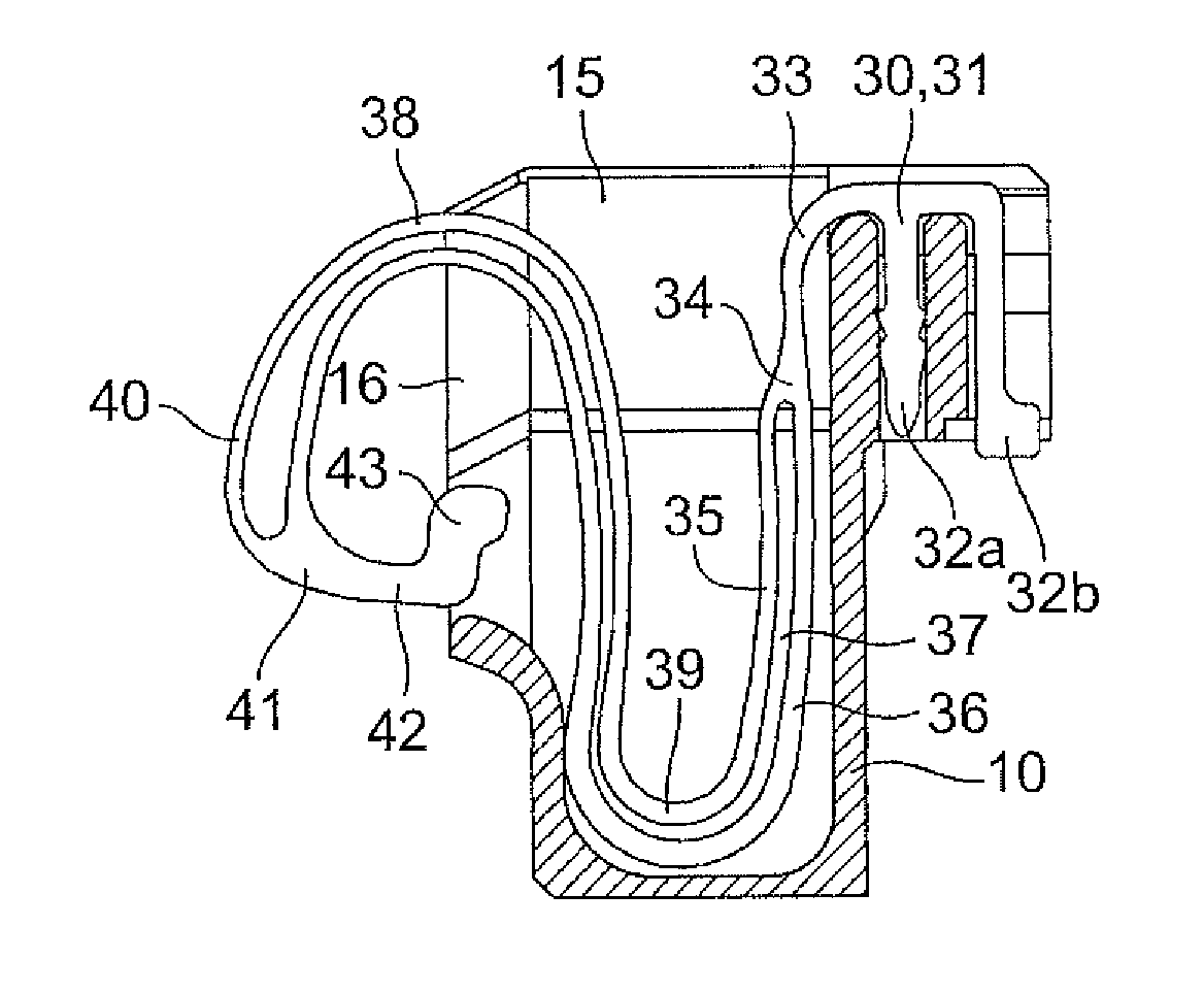
[0067]The connection terminal of the second embodiment was used as Example 1, and the connection terminal of the fifth embodiment was used as Example 2. The number of the operation times was measured until the connection terminal was broken by causing position controlling projections 44 of Examples 1 and 2 to abut on second extending portion 36.

[0068]As a result of the measurement, the average number of operation times of Example 2 became about five times that of Example 1. Therefore, usability of the abutment receiving portion was able to be confirmed because of the lengthened life.

[0069]The present invention is not limited to the embodiments described above. For example, the connector may of course be formed into a shape that can be surface-mounted on an upper surface of the printed board.

[0070]While the invention has been described with respect to a limited number of embodiments, those skilled in the art, having benefit of this disclosure, will appreciate that other embodiments c...


PUM


Abstract

A connection terminal has a movable contact portion that protrudes so as to be able to be pressed from an outside of a contact hole of a housing, and a first curved portion and a second curved portion that are continuously disposed and form a substantial S-shape. The movable contact portion is provided in a free end portion of the first curved portion. A position controlling projection extends from the movable contact portion. The position controlling projection abuts on an inner circumferential surface of the first curved portion or a region where the first curved portion and the second curved portion are continuously coupled to each other when the movable contact portion is pressed.

Description

BACKGROUND[0001]1. Technical Field[0002]The present invention relates to a connection terminal, for example to a connection terminal that not only is incorporated in a housing to constitute a connector but also can be used while directly mounted on a laterally end surface of a board.[0003]2. Related Art[0004]As to the conventional connection terminal, for example, there is an IC socket contact in which a core portion and a terminal contact portion are integrally formed while a spring side portion coupled to a support side portion is interposed therebetween. In the IC socket contact, the spring side portion has a horizontally substantial U-shape including an upper piece arm extending from the coupling portion to the terminal contact portion and a lower piece arm extending to the core portion, the upper piece arm includes first and second spring portions that extend in parallel while separating from each other, the lower piece arm includes third and fourth spring portions that extend ...

Claims


Application Information

Patent Timeline
Patent Type & Authority Patents(United States)
IPC IPC(8): H01R4/48H01R13/24H01R13/11
CPCH01R13/11H01R13/2428
Inventor KOYAMA, JIROTERANISHI, HIROTADASAKAI, TAKAHIRO
Owner ORMON CORP
Why Eureka
Try Eureka