Method for developing a sensing system to measure the attractive force between a magnetic structure and its target by quantifying the opposing residual magnetic field (ORMF)

a sensing system and magnetic structure technology, applied in the direction of magnetic bodies, magnetic field measurement using permanent magnets, instruments, etc., can solve the problems of distorted flux field on the target side, and achieve the effect of improving accuracy, improving accuracy, and improving accuracy

Active Publication Date: 2016-09-27
MAGLOGIX
View PDF24 Cites 7 Cited by
  • Summary
  • Abstract
  • Description
  • Claims
  • Application Information

AI Technical Summary

Benefits of technology

[0011]It is known that a permanent magnet has a north and south pole. However, a Magnetic Structure (referred to as a Core Element in prior art U.S. Pat. No. 8,183,965 B2 (Inventor Michael, 2013) also maintains the north and south pole structures of the magnet. In this configuration, the magnetic field or flux can be readily manipulated into and out of a ferrous Target. This Magnetic Structure is therefore capable of redirecting all of its magnetic flux through a ferrous Target capable of absorbing all of the available flux. Unlike prior art inventions that attempt to measure how much flux is absorbed by a Target, this invention quantifies the remaining flux level on the side opposite the Target. By doing this, far greater accuracy is achieved, as the flux levels on the opposite side of the Target are far more responsive and much easier to quantify than the flux level on the Target side. The flux field on the Target side is often distorted when the material thickness is incapable of fully absorbing the field. The prior art magnetic field sensors then attempt to measure a field in a thin ferromagnetic Target in addition to the field passing through the Target as well as the field outside of the Target. Unless the Target is relatively flat, inflexible, unpainted (no air-gap) and homogenous, the sensor output will fluctuate considerably. The instant invention greatly simplifies the ability to accurately quantify the magnetic attachment level by looking at how much of the field is actually absorbed by the Target. Furthermore, the instant invention provides sensor readings at any time during and after activation rather than just at the time of activation. This allows for a highly dynamic sensing system capable of continuously monitoring any changes or fluctuations to the magnetic attachment force.

Problems solved by technology

The flux field on the Target side is often distorted when the material thickness is incapable of fully absorbing the field.

Method used


Image

  • Method for developing a sensing system to measure the attractive force between a magnetic structure and its target by quantifying the opposing residual magnetic field (ORMF)
  • Method for developing a sensing system to measure the attractive force between a magnetic structure and its target by quantifying the opposing residual magnetic field (ORMF)
  • Method for developing a sensing system to measure the attractive force between a magnetic structure and its target by quantifying the opposing residual magnetic field (ORMF)

Examples


Embodiment Construction

Foundation

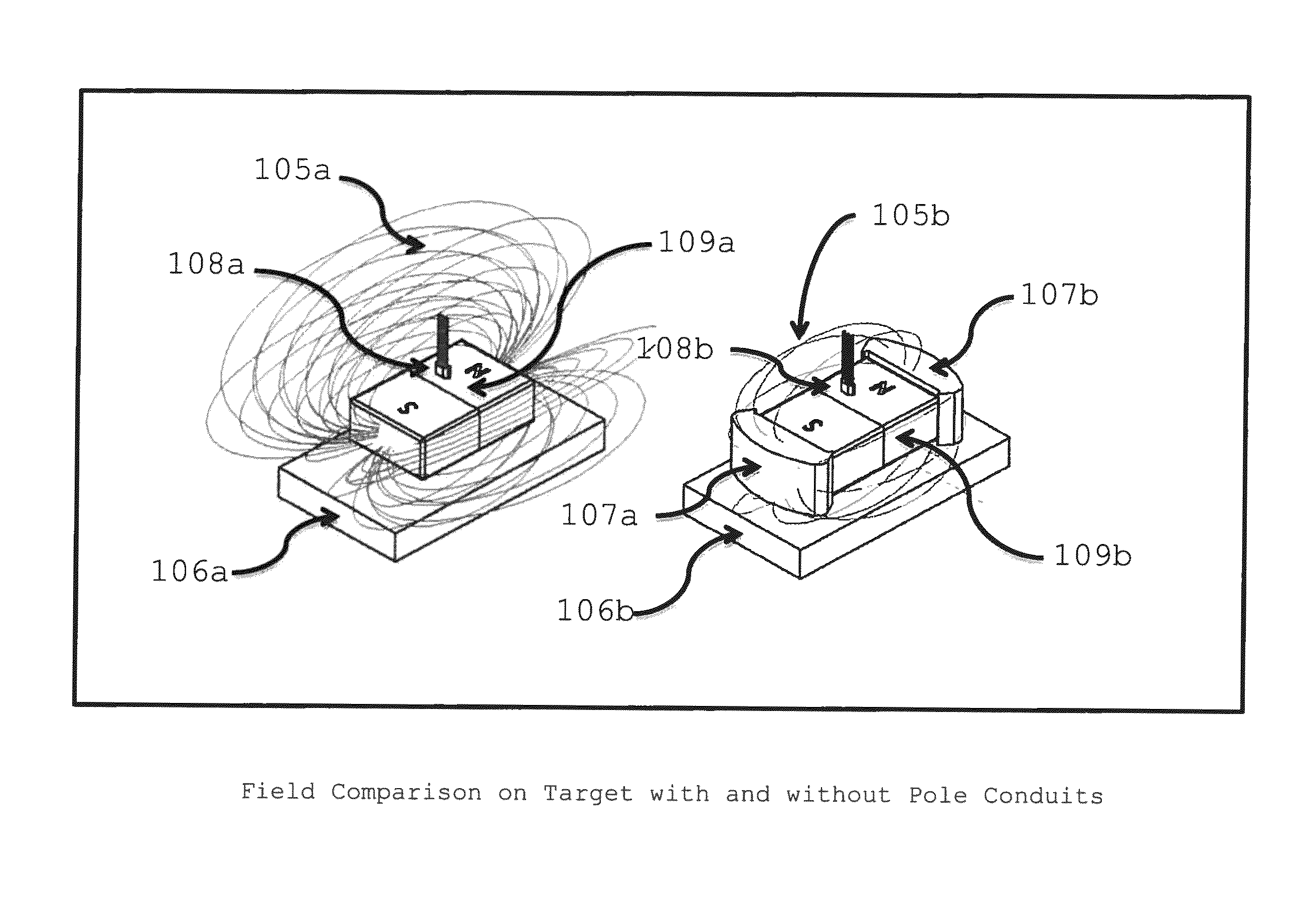
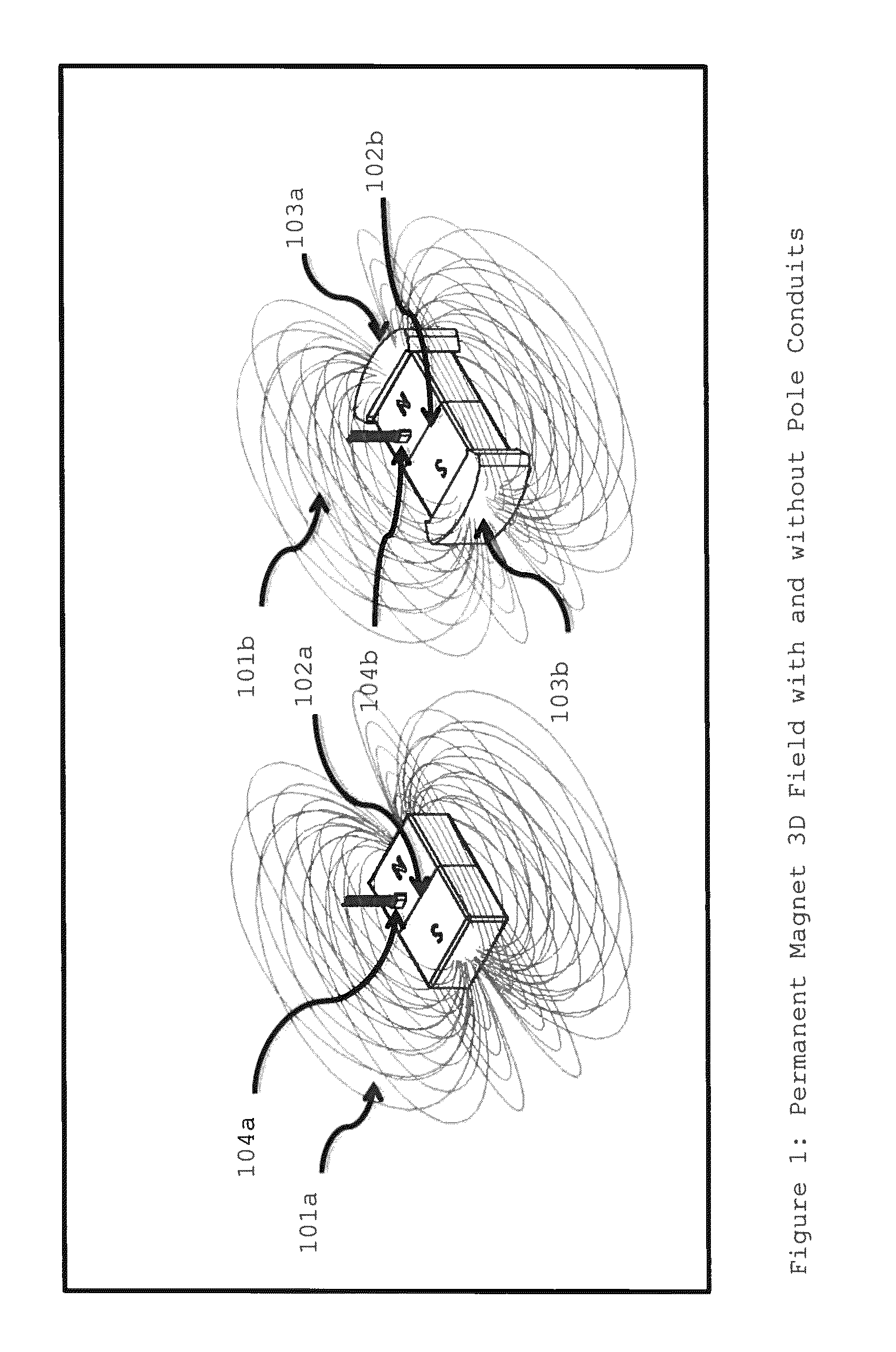
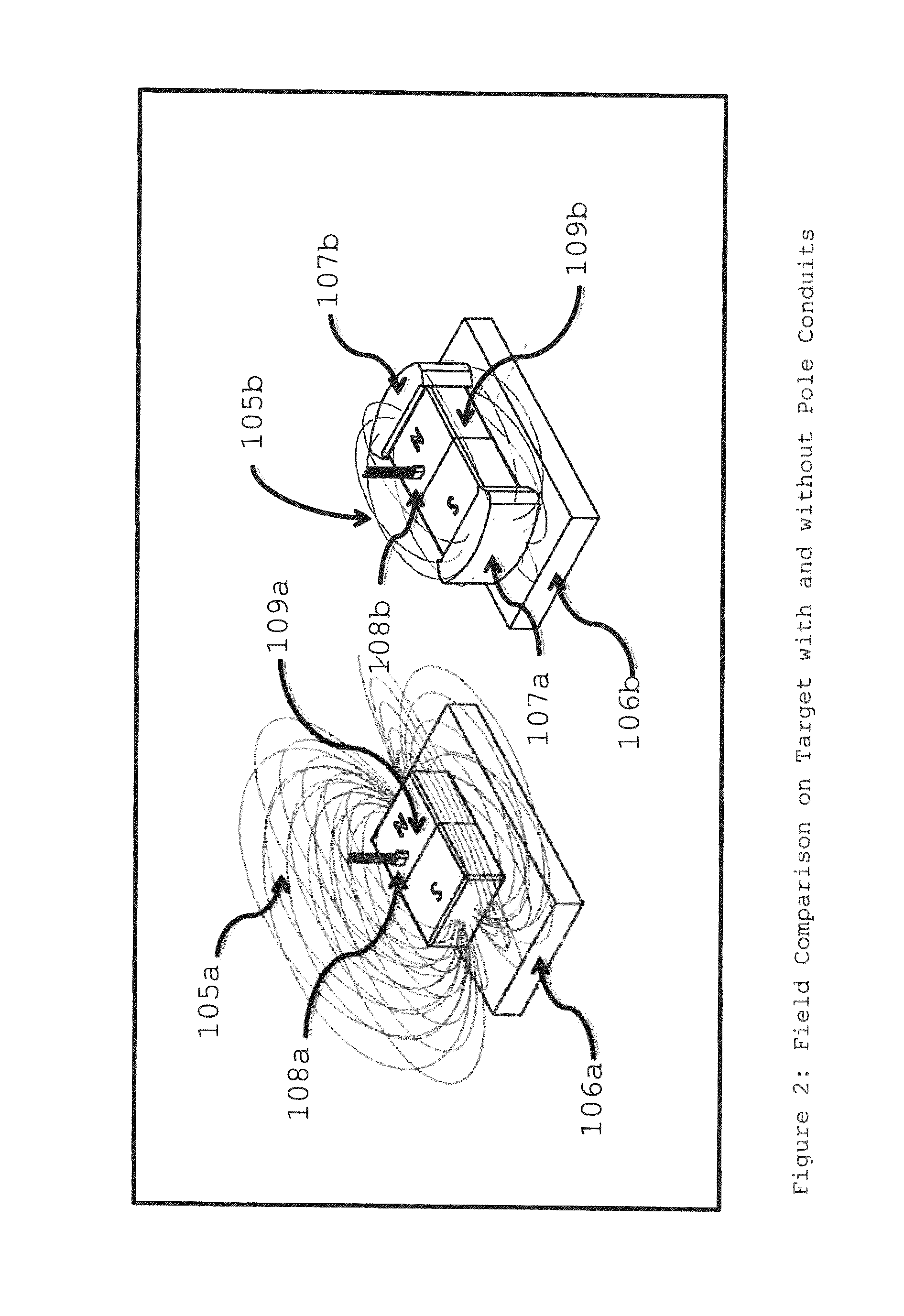
[0031]FIG. 1 depicts two identical permanent magnets, one with pole conduits (the right side of FIG. 1) and the other without (the left side of FIG. 1). For a detailed explanation and understanding of pole conduits, refer to U.S. Pat. No. 8,183,965 B2 (Inventor Michael) (2012) and U.S. Pat. No. 8,256,098 B2 (Inventor Michael (2012). A Sensor is placed along the magnetic field line above the permanent magnet to detect the magnetic field passing perpendicularly to the magnetic field plane. Magnetic field or flux lines are depicted in three-dimensional space traveling from one pole face or pole conduit to the other. In a preferred embodiment, the Sensor is a Hall Effect Sensor.

[0032]One skilled in the art of magnetics can readily design the relative size and composition of the pole conduits. Pole conduits can be made of a wide range of ferrous materials that have a relative permeability substantially greater than the relative permeability of the permanent magnets. As an examp...


PUM

PropertyMeasurementUnit
thicknessesaaaaaaaaaa
outer diameteraaaaaaaaaa

Abstract

The subject of this patent is a novel method for developing a sensing system that can determine a magnetic attraction force between a magnetic structure and its target level by using an Opposing Residual Magnetic Field (ORMF) to quantify said magnetic attraction force. Steps for the development and implementation of an ORMF Sensing System are set forth herein.

Description

[0001]Pursuant to 35 U.S.C. §119, the patent application comprising this specification claims the benefit of the filing date of a provisional application, USPTO application Number 62041352, filed Aug. 25, 2014.BACKGROUND OF THE INVENTION[0002]1. Field of the Invention[0003]There is a growing need for a quantitative means to determine the magnetic force generated between a Magnetic Structure (a permanent magnet with pole conduits (properly sized high permeability ferromagnetic material) placed on the magnetic pole faces) and its Target (the ferromagnetic material to which the Magnetic Structure attaches). This need has not been adequately met due to deficiencies in current technology.[0004]2. Prior Art[0005]U.S. Pat. No. 4,237,455 issued to Beckley et al. (1980), Improvements in Safety Device for Lifting Magnets (“the '455 patent”), describes a magnetic field flux sensor combined with a load cell, to provide an output that is indicative of the safety margin between lifting tension an...

Claims


Application Information

Patent Timeline
Patent Type & Authority Patents(United States)
IPC IPC(8): G01D1/00G01L1/12B23Q3/15H01F7/02G01R33/00G01R33/038
CPCG01L1/122B23Q3/15G01R33/00G01R33/0385H01F7/02H01F7/0294G01D5/147
Inventor MICHAEL, JIM G.
Owner MAGLOGIX
Why Eureka
Try Eureka