
Adsorptive permeation hollow fiber membrane, method of manufacturing the same, and gas adsorptive/desorptive separation system utilizing the same

a technology of hollow fiber membrane and permeation, which is applied in the direction of membranes, separation processes, membranes, etc., can solve the problems of reducing contact efficiency, excessive energy consumption for absorbing liquid regeneration, corrosion of absorbing liquid, etc., and achieves rapid regeneration, increase adsorption area, and contact efficiency

Active Publication Date: 2016-09-20
SEPRATEK
View PDF53 Cites 3 Cited by
  • Summary
  • Abstract
  • Description
  • Claims
  • Application Information

AI Technical Summary

Benefits of technology

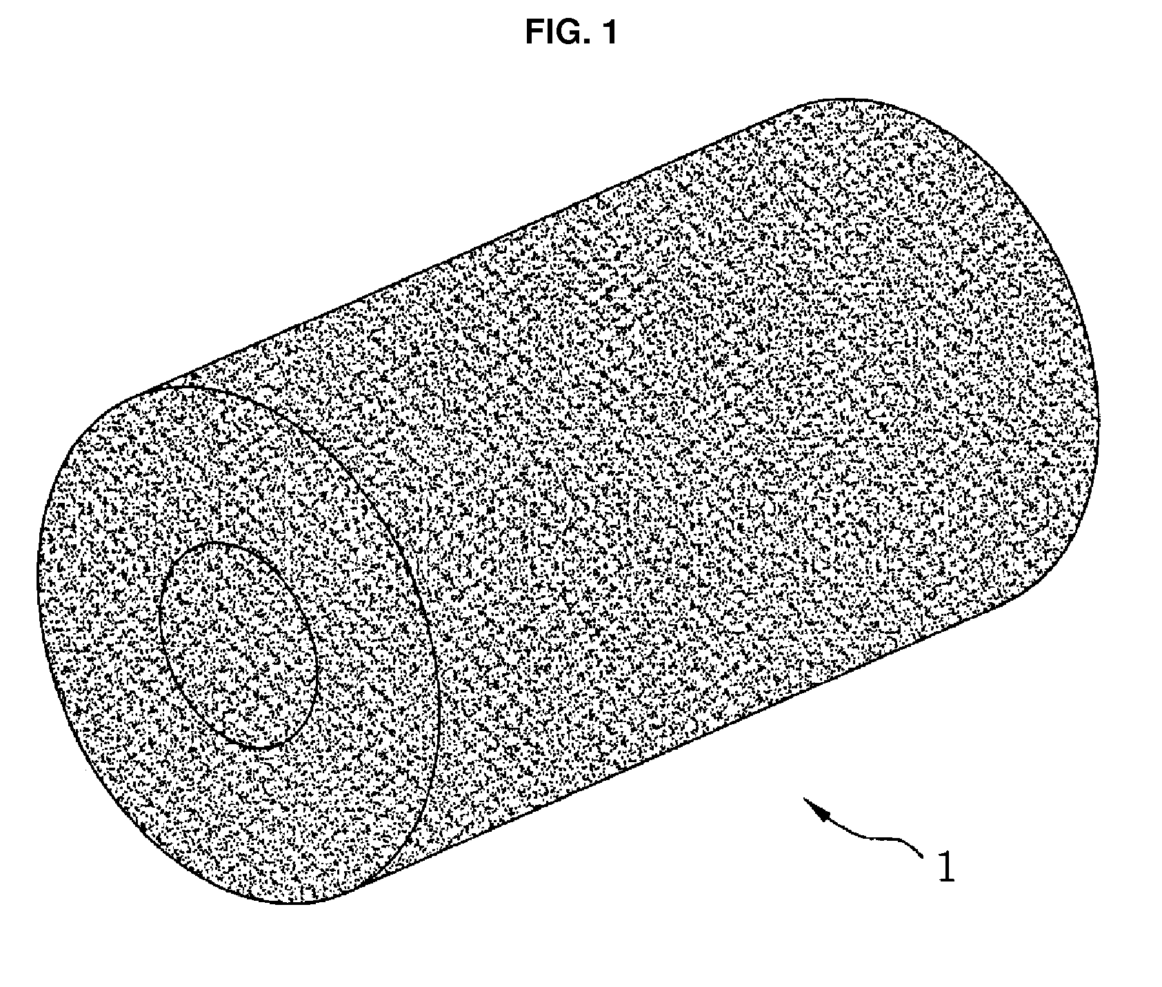
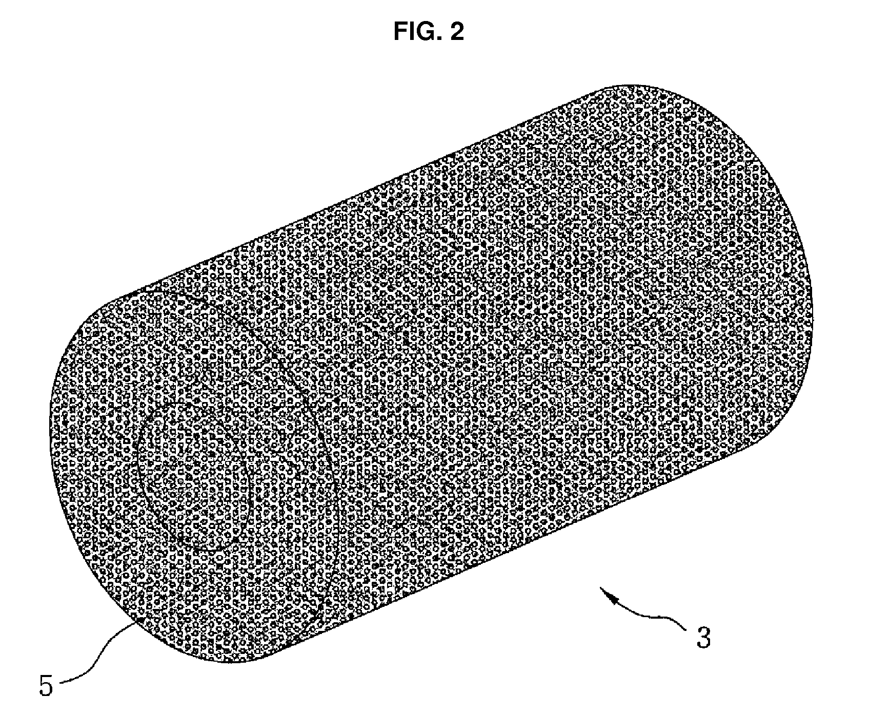
The membrane enables efficient gas separation with uniform contact between adsorbents and gases, quick regeneration, and reduced energy consumption, allowing for scalable separation systems from small to bulk applications.

Problems solved by technology

However, the absorption method has a number of problems such as excessive energy consumption for regeneration of the absorbing liquid, the overflow and channeling phenomenon of absorbing liquid in the absorption tower, a small gas-liquid contact area, and corrosion of the absorbing liquid.
The adsorption method is a method to adsorb the gas to be separated while allowing the mixed gas to pass through the bed filled with an adsorbent such as zeolite and has been applied to some gas treatment processes along with the study on various adsorbents, but the adsorption method has disadvantages that the use of a powdery adsorbent is limited due to the scattering problem and thus a granular adsorbent is used to have a decrease in contact efficiency, the flow velocity of the mixed gas in the bed is fast in the center and slow on the periphery and thus the adsorption mainly proceeds in the center to have a limited adsorption amount as compared to the amount of the adsorbent used, and it takes a long time to regenerate the adsorbent.
The membrane separation method is a separation method that utilizes a hollow fiber membrane capable of selectively permeating a portion of the mixed gas and has disadvantages that it takes an excessively long time and excessive energy is consumed to separate the gas since the membrane permeation speed of the gas is slow and a high pressure is required to be applied.

Method used


Image

  • Adsorptive permeation hollow fiber membrane, method of manufacturing the same, and gas adsorptive/desorptive separation system utilizing the same
  • Adsorptive permeation hollow fiber membrane, method of manufacturing the same, and gas adsorptive/desorptive separation system utilizing the same
  • Adsorptive permeation hollow fiber membrane, method of manufacturing the same, and gas adsorptive/desorptive separation system utilizing the same

Examples


examples

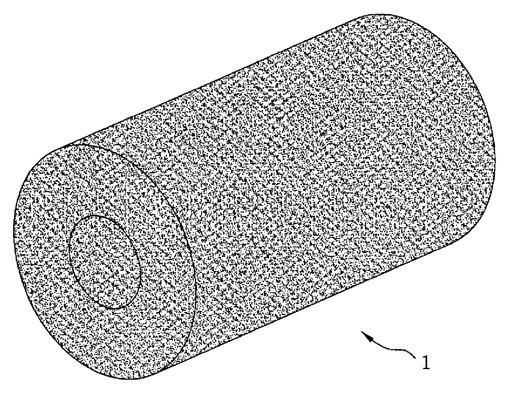
[0061]In Examples, polypropylene was used as the dope solution, a solution of latent solvent and non-solvents was used as the diluent, and zeolite 5A was used as the adsorbent. The thermally induced phase preparation process (TIPS) was used as the hollow fiber spinning method in the membrane manufacturing process. In this spinning method, twin-screw extrusion was adopted for mixing the dope solution. The spinning temperature was maintained at 220° C. The cooling speed was controlled at a speed at which a porous membrane capable of permeating both carbon dioxide and nitrogen can be formed. FIG. 17 is a scanning electron microscope (SEM) image for the cross section of the adsorptive permeation hollow fiber membrane manufactured by the present Example. FIG. 18 is a scanning electron microscope (SEM) image for the outer surface of the adsorptive permeation hollow fiber membrane manufactured by the present Example. FIG. 19 is a scanning electron microscope (SEM) image for the inner surfa...


PUM

PropertyMeasurementUnit
sizeaaaaaaaaaa
sizeaaaaaaaaaa
temperatureaaaaaaaaaa

Abstract

Disclosed are an adsorptive permeation hollow fiber membrane formed by uniformly dispersing an adsorbent capable of selectively adsorbing only a specific gas in mixed gas components inside a porous hollow fiber membrane having a sponge structure capable of non-selectively permeating a mixed gas in a powder or crystalline powder form, a method of manufacturing the same, and a gas adsorptive / desorptive separation system utilizing the same.

Description

REFERENCE TO RELATED APPLICATIONS[0001]This is a continuation of pending International Patent Application PCT / KR2014 / 002065 filed on Mar. 12, 2014, which designates the United States and claims priority of Korean Patent Application No. 10-2013-0095640 filed on Aug. 12, 2013, the entire contents of which are incorporated herein by reference.FIELD OF THE INVENTION[0002]The present invention relates to an adsorptive permeation hollow fiber membrane, in more detail, it relates to an adsorptive permeation hollow fiber membrane capable of effectively separating carbon dioxide and an acid gas contained in exhaust gases discharged from power plants, factories, chemical processes and the like or a general gas mixture and the like, a method of manufacturing the same, and a gas adsorptive / desorptive separation system utilizing the same.BACKGROUND OF THE INVENTION[0003]As the separation and recovery method of carbon dioxide, an absorption method, an adsorption method, a membrane separation meth...

Claims


Application Information

Patent Timeline
Patent Type & Authority Patents(United States)
IPC IPC(8): B01D53/22B01D53/04B01D69/02B01D71/26B01D71/68B01D69/14B01D69/08B01D53/047
CPCB01D53/228B01D53/0407B01D53/229B01D69/02B01D69/08B01D69/087B01D69/147B01D71/26B01D71/68B01D53/0476B01D2253/102B01D2253/108B01D2256/10B01D2257/504B01D2325/026B01D2325/12Y02C10/08Y02C10/10Y02C20/40B01D71/261
Inventor YEOM, CHOONG KYUNPARK, BYUNGJAE
Owner SEPRATEK
Learn More