Eureka AIR delivers breakthrough ideas for toughest innovation challenges, trusted by R&D personnel around the world.

Release apparatuses with locking surfaces formed at contact angles and methods of manufacturing release apparatuses

a technology of locking surface and release apparatus, which is applied in the direction of mechanical apparatus, vessel construction, transportation and packaging, etc., can solve the problem that the cutting of chain or cable can take a relatively long amount of tim

Active Publication Date: 2016-09-13
INTEROCEAN SYST LLC
View PDF11 Cites 4 Cited by
  • Summary
  • Abstract
  • Description
  • Claims
  • Application Information

AI Technical Summary

Benefits of technology

This patent describes a way to release two objects that are connected by tethers. The method involves using a hydraulic system with a bypass valve. When the bypass valve is open, hydraulic fluid can be drained from a conduit, which reduces pressure and allows the release apparatus to separate the two objects. This happens without causing excessive movement of the locking shoes, which maintain the objects in a locked position when under tension. The method also involves activating release valves to release the hydraulic fluid and closing the bypass valve to prevent further hydraulic fluid from exiting through it. The technical effects of this invention are a more efficient and reliable way to release objects connected by tethers, with improved safety and reliability.

Problems solved by technology

While these ways may be somewhat effective for some circumstances, there are limits such as in the length of chain or cable that can be run out, the cutting of chain or cable can take a relatively long amount of time because the chain or cable are typically relatively large, e.g., the thickness of the metal in the links can be three inches or more.

Method used


Image

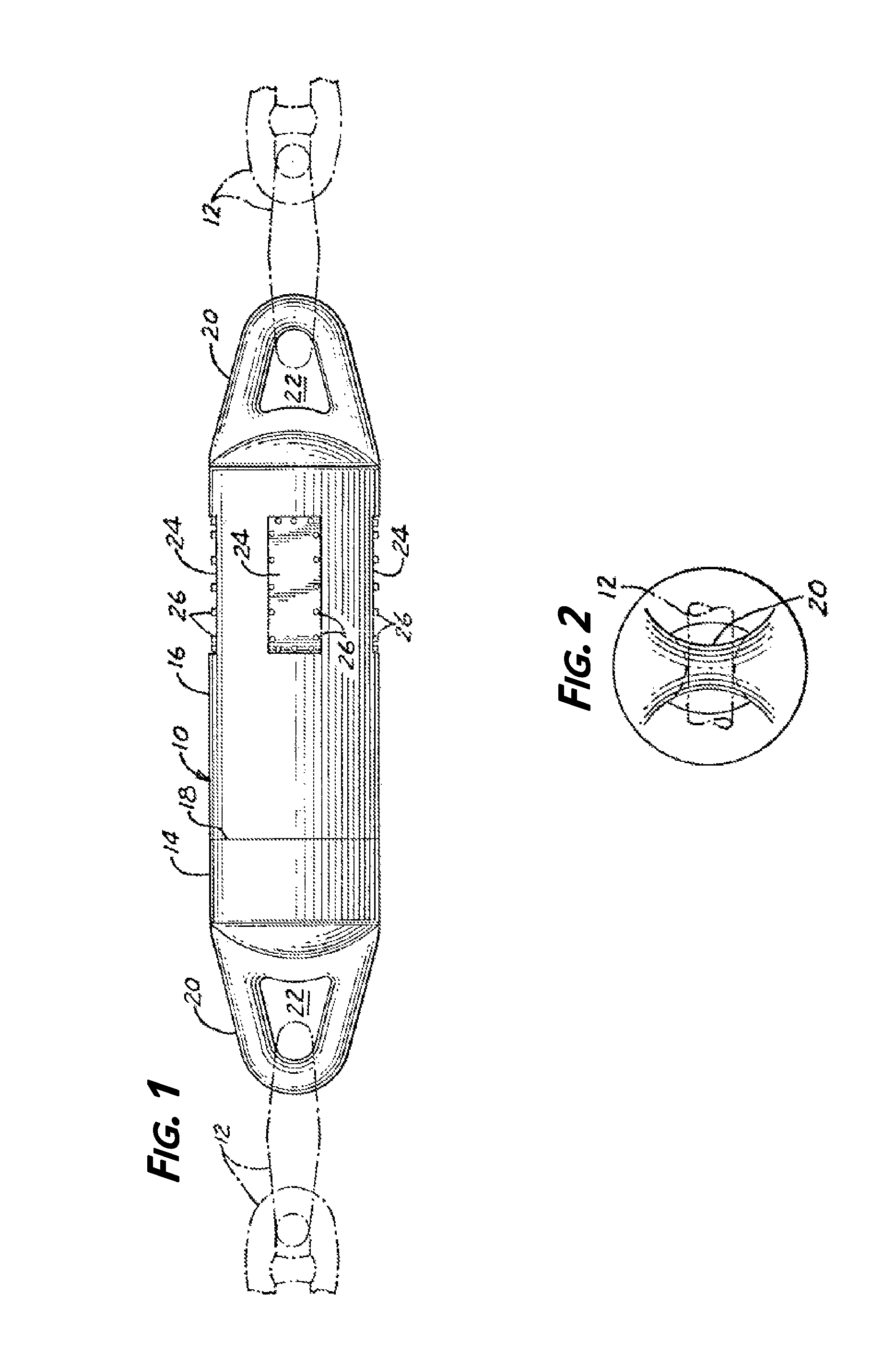
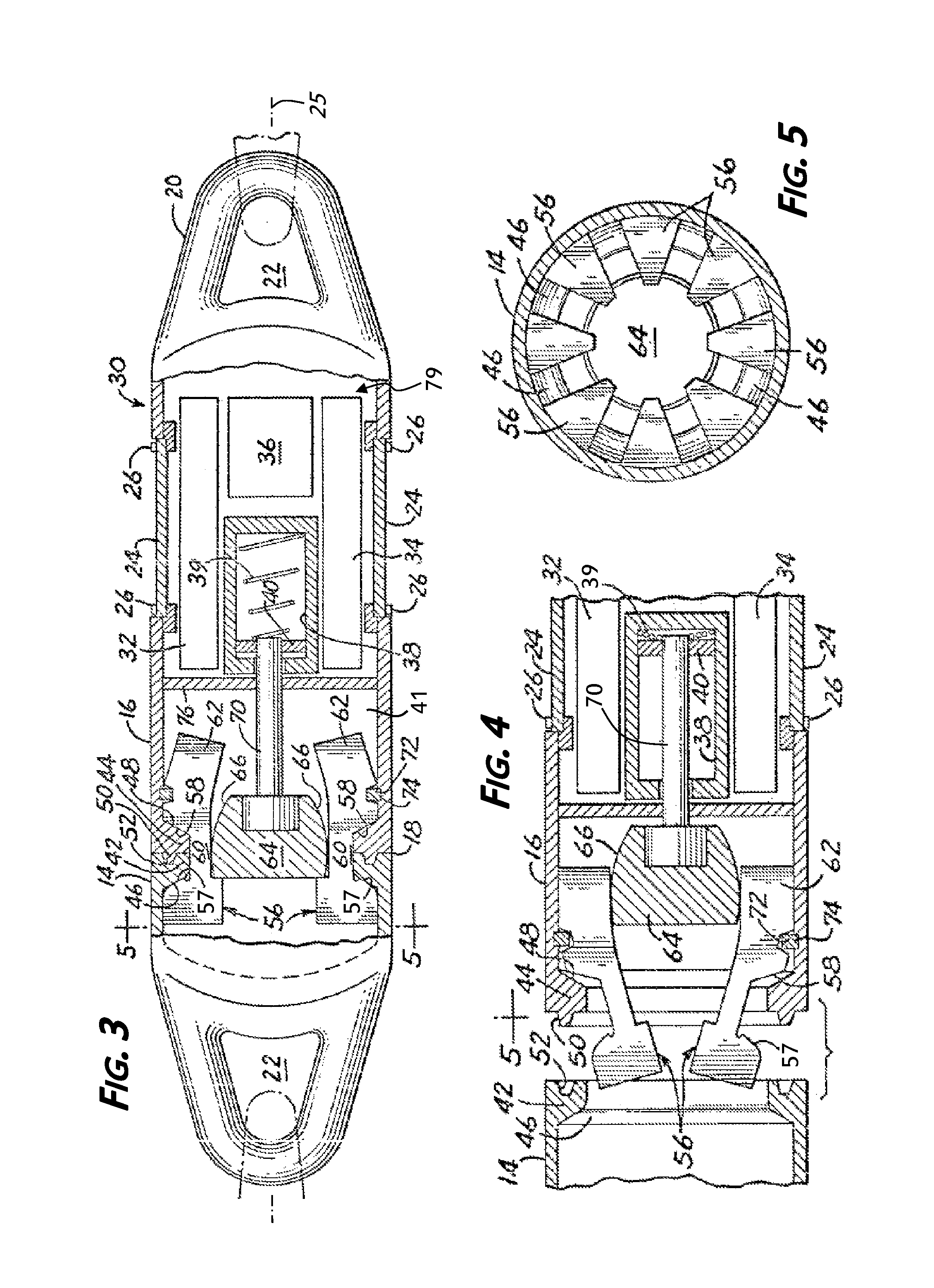
  • Release apparatuses with locking surfaces formed at contact angles and methods of manufacturing release apparatuses
  • Release apparatuses with locking surfaces formed at contact angles and methods of manufacturing release apparatuses
  • Release apparatuses with locking surfaces formed at contact angles and methods of manufacturing release apparatuses

Examples


example

[0094]Below is an example of an implementation of the heat treating process 1010, in accordance with some embodiments. One or more locking shoes, and typically a plurality of locking shoes are spaced on one or more racks or the like and positioned within an oven that includes calibrated thermocouples (e.g., a GM Enterprise endothermic oven, model GMA242436), with a temperature controller (e.g., from Honeywell International, Inc.). In some implementations, the locking shoes are cleaned (e.g., using a solvent) and labeled. The locking shoes are formed from a SAE alloy E4140 steel or similar alloy comprise 0.38-0.43 Carbon, 0.75-1.00 Manganese, 0.20-0.35 Silicon, less than or equal to 0.04 Phosphorus, less than or equal to 0.04 Sulfur, 0.80-1.10 Chromium, and 0.15-0.25 Molybdenum.

[0095]In step 1012, the oven is closed and an endothermic atmosphere is created (e.g., through a natural gas Lindberg 500 CFH generator) by extracting air and introducing methane gas, and the locking shoes are...


PUM


Abstract

Some embodiments provide release apparatuses comprising: a body comprising a first mating section and a second mating section connected to first and second tethers; and a plurality of movable locking shoes secured with the first mating section and movable between a first position configured to lock the first mating section and the second mating section together and a second position configured to allow the first mating section and the second mating section to disconnect; wherein each of the plurality of locking shoes comprises a locking surface configured to contact an engagement surface of the second mating section and maintain a position of the first mating section with the second mating section when the plurality of locking shoes are in the first position, and wherein the locking surface of each of the plurality of locking shoes is formed at a contact angle between about 18 degrees and 24 degrees.

Description

[0001]This application relates to the following applications filed concurrently herewith. The related applications are: U.S. patent application Ser. No. 14 / 604,214, of Michael D. Pearlman, entitled Release Apparatus and Method of Manufacturing a Release Apparatus, which is incorporated in its entirety herein by reference; U.S. patent application Ser. No. 14 / 604,241, of Michael D. Pearlman, entitled Methods of Manufacturing Release Apparatuses, which is incorporated in its entirety herein by reference; and U.S. patent application Ser. No. 14 / 604,285, of Michael D. Pearlman, entitled Release Apparatuses Comprising a Hydraulic System and Methods of Manufacturing Release Apparatuses, which is incorporated in its entirety herein by reference.BACKGROUND[0002]1. Field of the Invention[0003]The present invention relates generally to release apparatuses, and more specifically to relatively large load release apparatuses.[0004]2. Discussion of the Related Art[0005]Relatively thick and / or larg...

Claims


Application Information

Patent Timeline
IPC IPC(8): B66C1/34F16G15/04B63B21/20
CPCF16G15/04B63B21/20B63B2021/203B63B21/08B63B2021/004B63B2021/007B63B2205/00F16G11/00
Inventor PEARLMAN, MICHAEL D.
Owner INTEROCEAN SYST LLC
Why Eureka
Eureka Blog
Learn More