
Integrated circuit system with tunable resistor and method of manufacture thereof

a technology of integrated circuits and resistors, which is applied in the direction of resistors, basic electric elements, solid-state devices, etc., can solve the problems of increasing costs, real challenge to change the process, and certain limitations of scalable resistors (p-cells)

Active Publication Date: 2016-08-16
ALTERA CORP
View PDF10 Cites 2 Cited by
  • Summary
  • Abstract
  • Description
  • Claims
  • Application Information

AI Technical Summary

Benefits of technology

The present invention provides a method of manufacturing an integrated circuit system with a discretized tunable precision resistor. The resistor has a total resistance that is a function of its length between two metal taps, which are connected to conductive metal strips. This allows for fine-tuning of the resistance and can be useful in various applications such as sensor networks or actuators. The method includes steps of forming an integrated circuit substrate, and then adding the resistor, interconnects, metal taps, and conductive metal strips. The "technical effect" of the invention is to provide a precise and easily adjustable resistor for integrated circuit systems.

Problems solved by technology

Further, it is a real challenge to change the process to meet the resistance accuracy requirements.
Any inaccuracy will require design changes and probably die size changes, which increase costs.
Unfortunately, scalable resistors (P-cell) have certain limitations.
This means a resistor footprint change is required if the resistance is off target.
Unfortunately, any discrepancy on the silicon die would require a whole template or fixed cell change.
Solutions to these problems have been long sought but prior developments have not taught or suggested any solutions and, thus, solutions to these problems have long eluded those skilled in the art.

Method used


Image

  • Integrated circuit system with tunable resistor and method of manufacture thereof
  • Integrated circuit system with tunable resistor and method of manufacture thereof
  • Integrated circuit system with tunable resistor and method of manufacture thereof

Examples


first embodiment

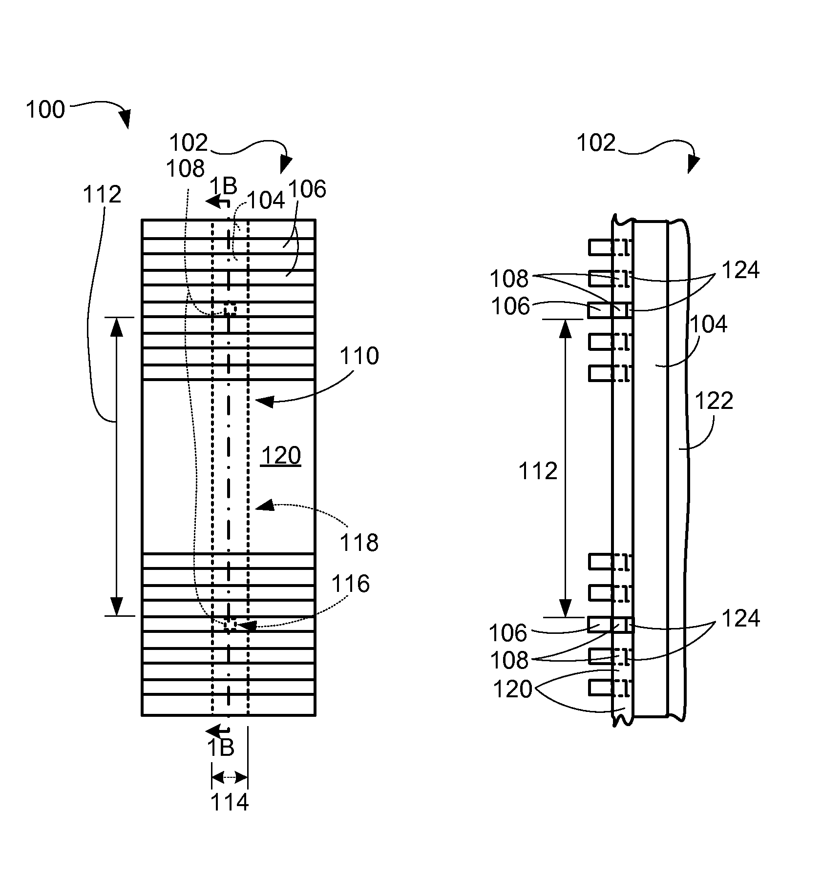
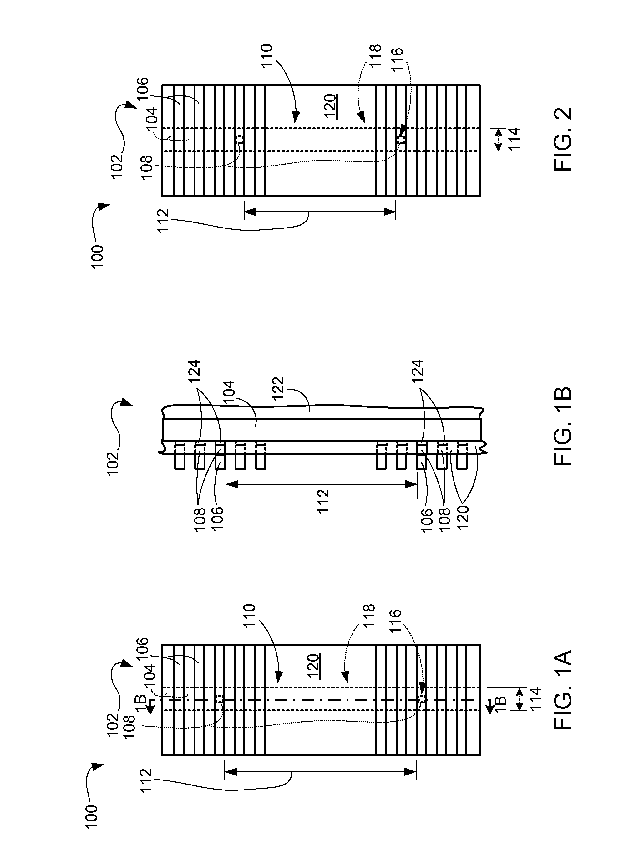
[0029]Referring now to FIG. 1A, therein is shown a top view of the present invention in a first configuration. The top view depicts an integrated circuit system 100 having a drawn resistor or a discretized tunable precision resistor 102.

[0030]The discretized tunable precision resistor 102 includes a high resistance resistor body 104. For example, the high resistance resistor body 104 is of a material such as polysilicon, titanium nitride (TiN), or a semiconductor metal gate material. Also for example, the high resistance resistor body 104 can be formed in a Silicide block region.

[0031]Conductive metal strips 106 are placed over the high resistance resistor body 104. A pair of metal taps 108 contacts two of the conductive metal strips 106. For example, the conductive metal strips 106 are of a metallic material, such as copper, aluminum, any other metallic material, or a metal alloy.

[0032]A total resistance 110 of the discretized tunable precision resistor 102 is a function of an acti...

second embodiment

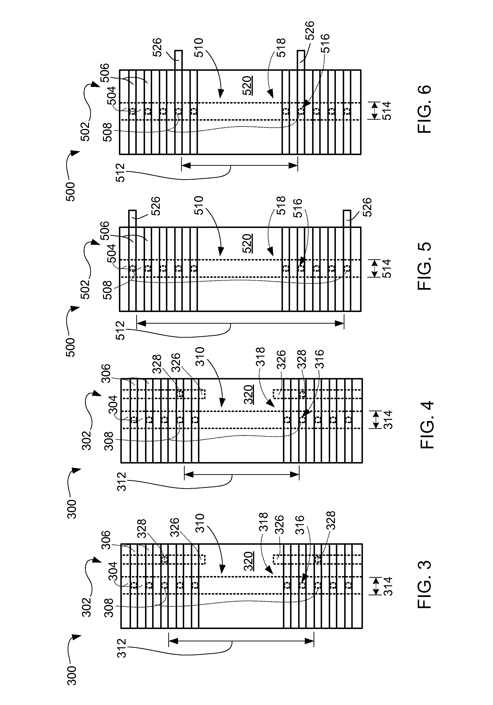
[0063]Referring now to FIG. 3, therein is shown a top view of the present invention in a first configuration. The top view depicts an integrated circuit system 300 having a discretized tunable precision resistor 302.

[0064]The discretized tunable precision resistor 302 includes metal taps 308, first conductive metal strips 306, and second conductive metal strips 326, and vias 328. The metal taps 308 are formed directly under a number or all of the first conductive metal strips 306. The metal taps 308 connect respective ones of the first conductive metal strips 306 with the resistor body of the discretized tunable precision resistor 302, as disclosed herein with respect to the metal taps 108 of FIG. 1B. The second conductive metal strips 326 are formed over the first conductive metal strips 306.

[0065]The second conductive metal strips 326 are formed approximately perpendicular to the first conductive metal strips 306. For example, the first conductive metal strips 306 can represent me...

third embodiment

[0079]Referring now to FIG. 5, therein is shown a top view of the present invention in a first configuration. The top view depicts an integrated circuit system 500 having a discretized tunable precision resistor 502. The discretized tunable precision resistor 502 includes first conductive metal strips 506 and second conductive metal strips 526. Metal taps 508 connect respective ones of the first conductive metal strips 506 with the resistor body of the discretized tunable precision resistor 502, as disclosed herein with respect to the metal taps 108 of FIG. 1B.

[0080]The second conductive metal strips 526 are formed adjacent or in direct contact with the first conductive metal strips 506. The second conductive metal strips 526 are coplanar with the first conductive metal strips 506.

[0081]For illustration purposes, the second conductive metal strips 526 are shown on the right of the first conductive metal strips 506, although it is understood that the second conductive metal strips 52...


PUM


Abstract

An integrated circuit system, and a method of manufacture thereof, includes: an integrated circuit substrate; and a discretized tunable precision resistor having a total resistance including: a resistor body over the integrated circuit substrate, interconnects directly on the resistor body, metal taps directly on the interconnects and at opposing sides of the resistor body, and conductive metal strips over the interconnects, wherein the total resistance is a function of an active resistor length of the resistor body between a pair of the metal taps in contact with two of the conductive metal strips.

Description

TECHNICAL FIELD[0001]The present invention relates generally to an integrated circuit system, and more particularly to a system for integrated circuits with resistors.BACKGROUND ART[0002]Accuracy of high precision resistors is important for many integrated circuit applications with, e.g., input / output (I / O) buffers. However, the accuracy of the actual integrated circuits to their mathematical models depends on foundry manufacturing processes used.[0003]Often times, it is necessary to design high precision resistors before it is possible to validate the accuracy of the model versus a mature foundry manufacturing process. Further, it is a real challenge to change the process to meet the resistance accuracy requirements.[0004]Any inaccuracy will require design changes and probably die size changes, which increase costs. In the end, it is often necessary to do layout redesigns and re-tapeout masks to meet the required resistance accuracy requirements. Die size change will impact overall...

Claims


Application Information

Patent Timeline
Patent Type & Authority Patents(United States)
IPC IPC(8): H01L27/01H01L23/522H01L27/06H01L49/02H01C10/08H01C10/23H01C1/14H10N97/00
CPCH01L27/0629H01L23/5228H01L28/20H01C10/08H01C10/23H01C1/14
Inventor LIM, QUEENNIE SUAN IMMWATT, JEFFREY T.CHEN, SHUXIAN
Owner ALTERA CORP
Learn More