Air curtain HVAC system

a technology of air curtain and hvac system, which is applied in the direction of lighting and heating apparatus, heating types, human health protection, etc., can solve the problems of reducing the efficiency of the system, and requiring manual cleaning and periodic replacement of the filter media of the conventional system, so as to reduce the amount of thermal energy exchange, reduce the amount of energy consumption, and improve the effect of energy efficiency

Inactive Publication Date: 2016-07-12
AIR VALUE SYST
View PDF8 Cites 2 Cited by
  • Summary
  • Abstract
  • Description
  • Claims
  • Application Information

AI Technical Summary

Benefits of technology

[0013]The invention relates to the improvements in the field of HVAC and indoor air pollution control, specifically providing a new and improved system for the delivery of a temperature controlled air supply via air curtains located at windows, doors and walls. The present invention also provides an improved system for cleaning the recycled air through the use of a wet electrostatic precipitator in the HVAC air flow, providing continuous air cleaning, without the problems of down time or labor for cleaning and replacement, and providing close to 100% efficiency in cleaning pollutants, particulate matter as small as 0.01 micron, bacteria and viruses from the air flow.
[0016]The basic climate control technology for a building using the proposed invention is similar to the conventional HVAC systems using thermostats to control heating and cooling units. As conventional HVAC systems utilize low velocity air flow delivery, the present invention provides for greater energy efficiency over existing air curtain systems.
[0017]The present invention provides energy savings directly attributed to the diminished amount of thermal energy exchange between the exterior and interior of the building.

Problems solved by technology

These impurities and particulate matter may be delivered by wind and precipitation, traveling from far distances, and contaminate the air and exterior spaces around the buildings.
Conventional HVAC systems employ air cleaning devices such as dry electrostatic precipitators and filters that at best remove only dust particles, but do not remove or isolate the long list of pollutants identified above.
Such conventional systems also require manual cleaning and periodic replacement of filter media.
Such extensive maintenance makes the use of conventional systems impractical.
Failure to clean these systems and / or to replace the filter media can drastically reduce the efficiency of these systems due to high pressure drop on the filters.
The current locations of such registers is not the optimum place for proper temperature control, as most energy losses take place at the windows and doors, where registers are not able to be located.
These temperature exchanges or thermal energy losses increase the cost of operating HVAC systems in a building.
As is known in the field of building construction, the use of insulating materials can decrease such temperature exchanges, but for existing structures, it may not be cost-effective to replace existing materials or add insulation within walls.
The thermal energy losses, both heat and cold, can be very substantial through windows in a building.
As the latest architectural practice calls for allocating at least 40% of exterior walls for windows, the potential for thermal energy loss can only increase.
Existing air curtains are high velocity blowers located in a large housing above the door producing substantial noise and requiring frequent cleaning and maintenance.
In addition to their bulk and being esthetically undesirable in the residential interior setting, these blowers are also noisy, require frequent cleaning and other routine maintenance as is usually required for high speed rotating machinery.
Even a small amount of dirt on the surface of the high speed rotating rotor creates dynamic misbalance leading to high noise and eventual damage to or destruction of the unit.
Existing air curtain systems are not feasible for use in residential or commercial office buildings.

Method used


Image

  • Air curtain HVAC system
  • Air curtain HVAC system
  • Air curtain HVAC system

Examples


Embodiment Construction

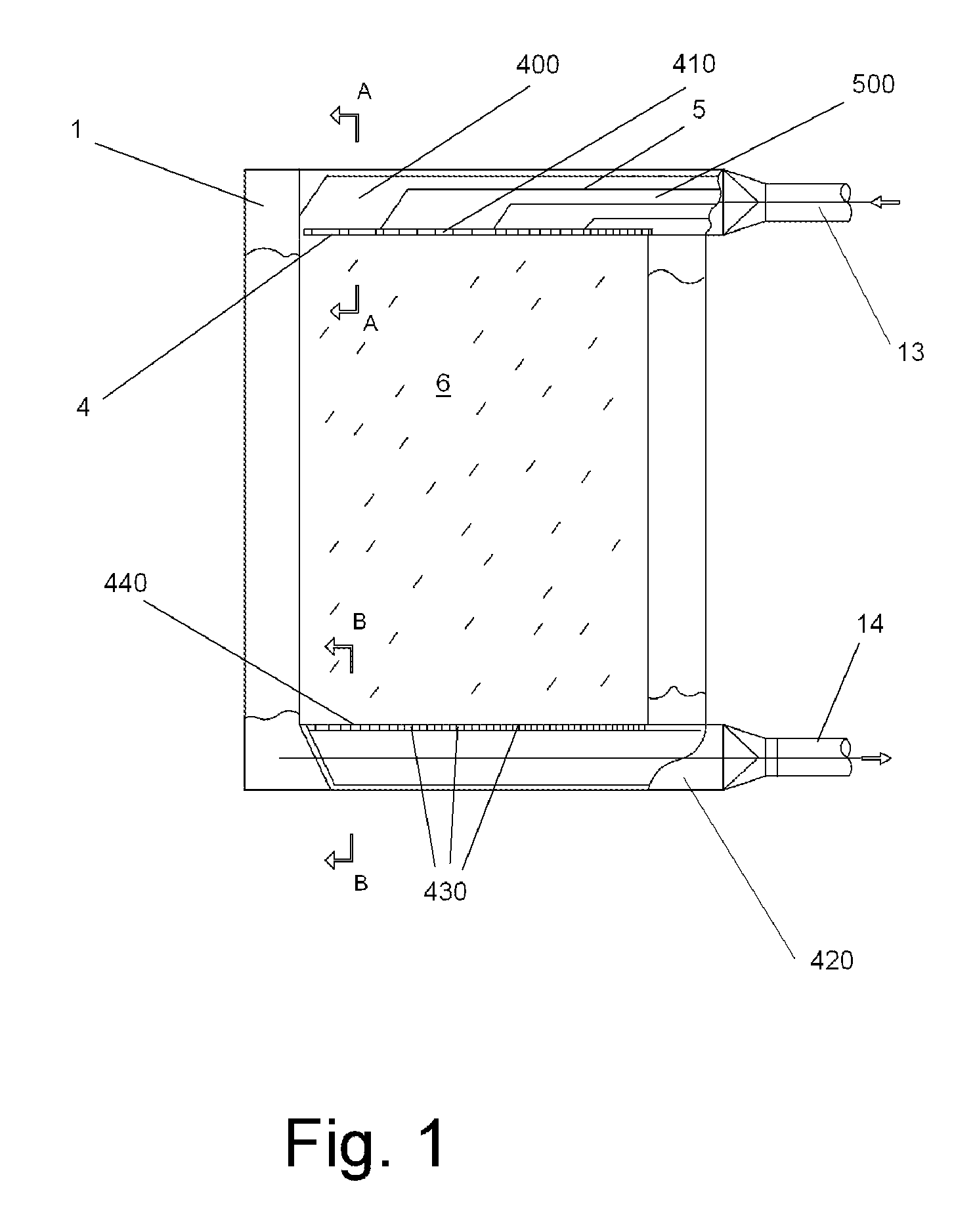
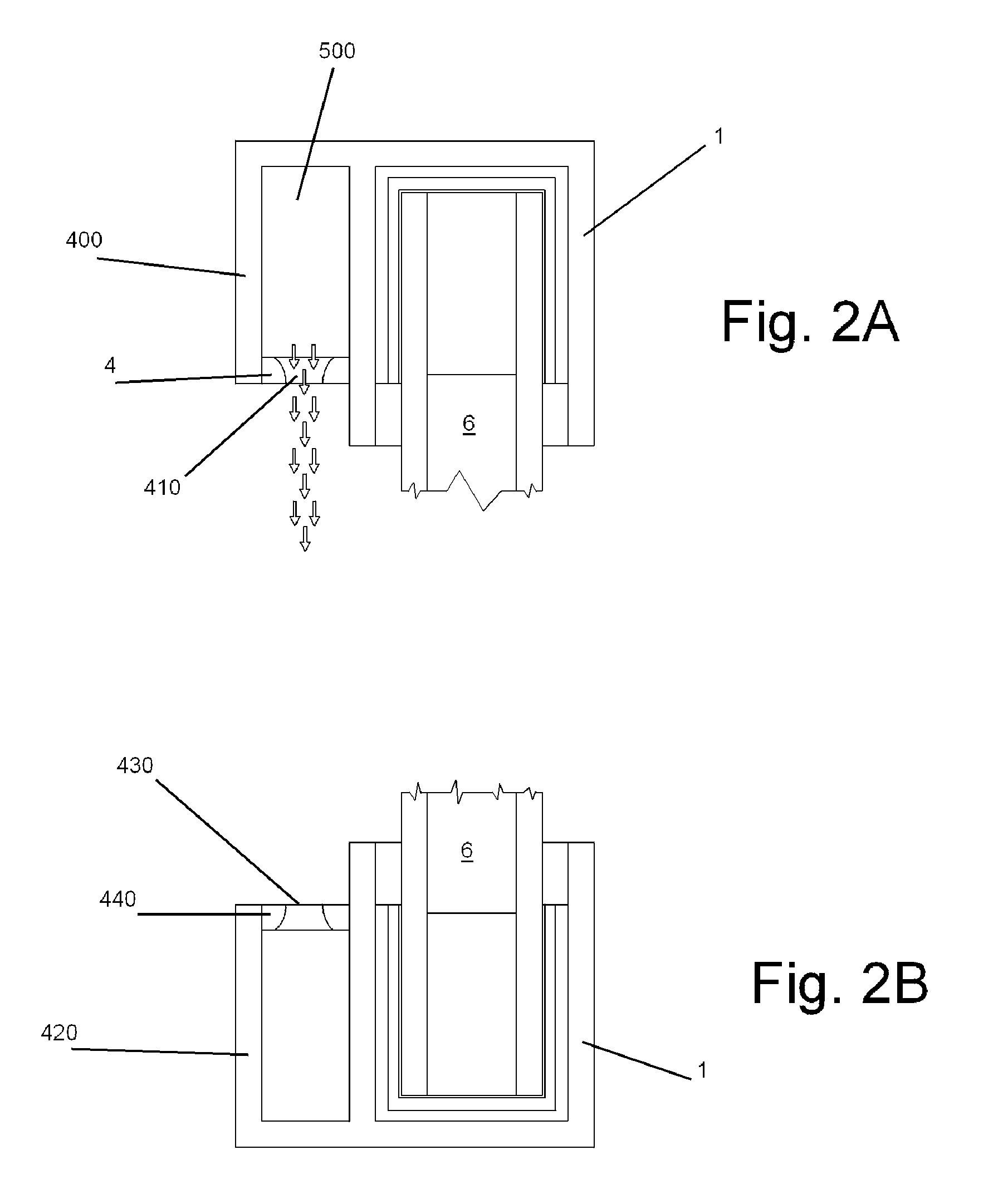
[0030]FIG. 1 depicts a single window frame 1 window pane 6. First chamber 400 and second chamber 420 are mounted on opposite sides of window frame 1, preferably above and below window pane 6. First chamber 400 is connected at one end to first duct 13 and has perforations 410 along wall 4. Air distribution manifold 500 is preferably located in first chamber 400. Vanes 5 are strategically located within air distribution manifold 500 and direct air flow toward perforations 410, preferably for equal air distribution of the air curtain stream along the surface of window pane 6.

[0031]Second chamber 420 may be of identical construction as first chamber 400, but is connected to second duct 14 instead of first duct 13. Second chamber 420 has perforations 430 along wall 440. As shown in FIG. 1, while first chamber 400 contains air distribution manifold 500, second chamber is depicted without optional feature air distribution manifold 500.

[0032]In one mode of operation, an air flow enters firs...


PUM


Abstract

An improved HVAC system is provided for the delivery of a temperature controlled air supply via one or more air curtains provided at windows, doors and walls. The air curtains create a double layer of insulation over the surface of a window, door or wall. The invention provides for the use of the temperature controlled air flow from the air curtain to directly affect the interior room temperature. The invention provides an improved system for continuous cleaning the recycled air through the use of a wet electrostatic precipitator in the HVAC air flow, as well as providing a higher speed mode for the air curtain to prevent the inflow of particles and contaminants from outside of the building, when windows or doors are open. The invention may be installed on existing construction, or incorporated as part of new construction.

Description

FIELD OF INVENTION[0001]A system is proposed for a central heating, ventilation and air conditioning (HVAC) system for residential and commercial buildings that will save energy for ventilation, heating or cooling by changing the thermal resistance R-value of the structural elements of the building, and also deliver clean air to the interior room environment. The proposed system will allow windows to be kept open, if desired, while preventing contaminants, dust and insects from entering the interior environment.BACKGROUND[0002]Contemporary HVAC systems are based on a combination of recycled air as well as the intake of ambient “clean and fresh” air that in reality may contain a variety of impurities and particulate matter, including pollutants, carcinogenic compounds, volatile organic compounds from vehicle exhaust, and a long list of toxic chemicals from any number of industrial sources. These impurities and particulate matter may be delivered by wind and precipitation, traveling f...

Claims


Application Information

Patent Timeline
Patent Type & Authority Patents(United States)
IPC IPC(8): B03C3/34F24F9/00B03C3/16B03C3/41
CPCF24F9/00B03C3/16B03C3/41B03C2201/10Y02A50/2351
Inventor RAY, ISAACBROWN, DAVIDBEYDER, IGOR
Owner AIR VALUE SYST
Why Eureka
Try Eureka