Cold effect applicator tip
a technology of applicator tips and cosmetic products, which is applied in the direction of packaging foodstuffs, nibs, packaged goods, etc., can solve the problems of reducing affecting the oxidation effect of cosmetic products, so as to reduce the oxidation risk of cosmetic products, reduce the risk of oxidation, and manufacture cheap
- Summary
- Abstract
- Description
- Claims
- Application Information
AI Technical Summary
Benefits of technology
Problems solved by technology
Method used
Image
Examples
example 1
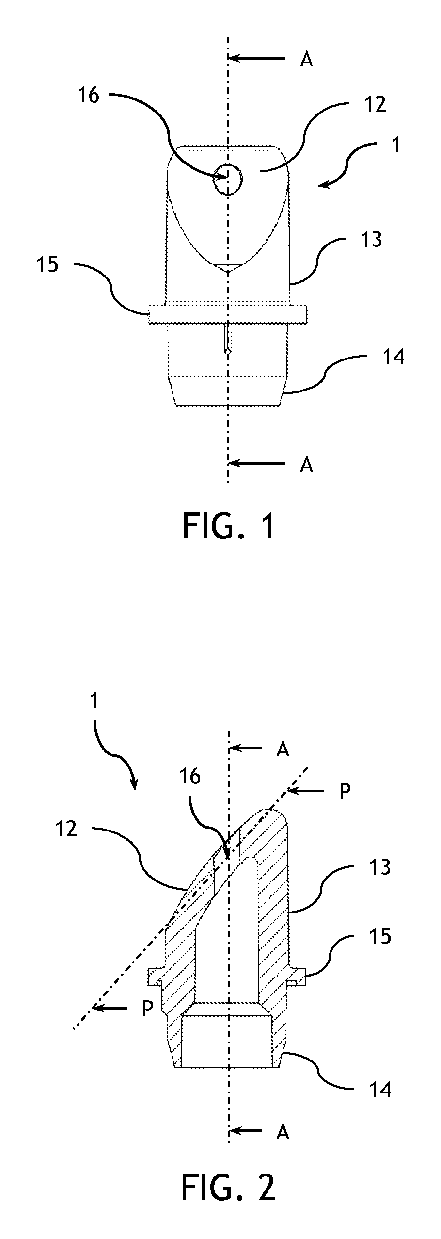
[0073]The applicator tip of example 1 comprises a convex external application surface having in its largest part a radius of curvature of 25 mm. Such application surface extends according to an inclined plane with respect to the axis of the applicator tip. The thickness of the material under the application surface is about 2.2 mm. The applicator tip comprises a ring wall of a thickness of 2.2 mm and is configured according to a cylindrical tube with a circular cross section which is beveled with an acute angle of 42° on one of the ends thereof according to the inclined plane. The external radius of the circular cross section is 9.8 mm.
[0074]On the other non beveled end of the tube, the edges of the ring wall are tapered so as to present a thickness of 1 mm.
[0075]A circular circumferential stop is provided around the ring wall and extends from the latter. The external radius of the circular circumferential stop is 12.5 mm.
[0076]The applicator tip presents a through orifice with a ra...
example 2
[0077]The applicator tip of example 2 comprises a convex external application surface having in its largest part a radius of curvature of 45 mm. Such application surface extends according to an inclined plane with respect to the axis of the applicator tip. The thickness of the material under the application surface is about 4.7 mm. The applicator tip comprises a ring wall with a thickness of 4.7 mm and is configured according to a cylindrical tube with a circular cross section which is beveled with an acute angle of about 42° on one of its ends according to the inclined plane. The external radius of the circular cross section is 9.8 mm.
[0078]On the other non beveled end of the tube, the edges of the ring wall are tapered so as to present a thickness of 2 mm.
[0079]A circular circumferential stop is provided around the ring wall and extends from the latter. The external radius of the circular circumferential stop is 11 mm.
[0080]Between the other end and the circumferential stop, the a...
example 3
[0082]Examples of metallic or organic filled plastic materials are given in the table 1 herein below.
[0083]
TABLE 1Plastic 1Plastic 2Plastic 3Plastic 4BasePEEKPPSPPAPA6Type of fillersOrganic:Organic:Organic:Metallic:carbon andcarbon andcarbon andmetalgraphitegraphitegraphitemineralfiberfiberfibersaltsQuantity of fillers40 wt %40 wt %40 wt %45 wt %Effusivity7370713057204010J · K−1 · m−2 ·sec−1 / 2Thermal22222010conductivityW / (m · K)Diffusivity m2 / sec8.99.512.26.2Volume weight1.641.651.561.6g / cm3
PUM
 Abstract
Description
Claims
Application Information
 - R&D
- Intellectual Property
- Life Sciences
- Materials
- Tech Scout
- Unparalleled Data Quality
- Higher Quality Content
- 60% Fewer Hallucinations
Browse by: Latest US Patents, China's latest patents, Technical Efficacy Thesaurus, Application Domain, Technology Topic, Popular Technical Reports.
© 2025 PatSnap. All rights reserved.Legal|Privacy policy|Modern Slavery Act Transparency Statement|Sitemap|About US| Contact US: help@patsnap.com


