
Handler for blowout preventer assembly

a technology for blowout preventers and handlers, which is applied in the field of handlers, can solve the problems of time-consuming and labor-intensive installation and connection of tools to tubing, and achieve the effect of safe work spa

Active Publication Date: 2016-05-31
NAT OILWELL VARCO LP
View PDF7 Cites 27 Cited by
  • Summary
  • Abstract
  • Description
  • Claims
  • Application Information

AI Technical Summary

Benefits of technology

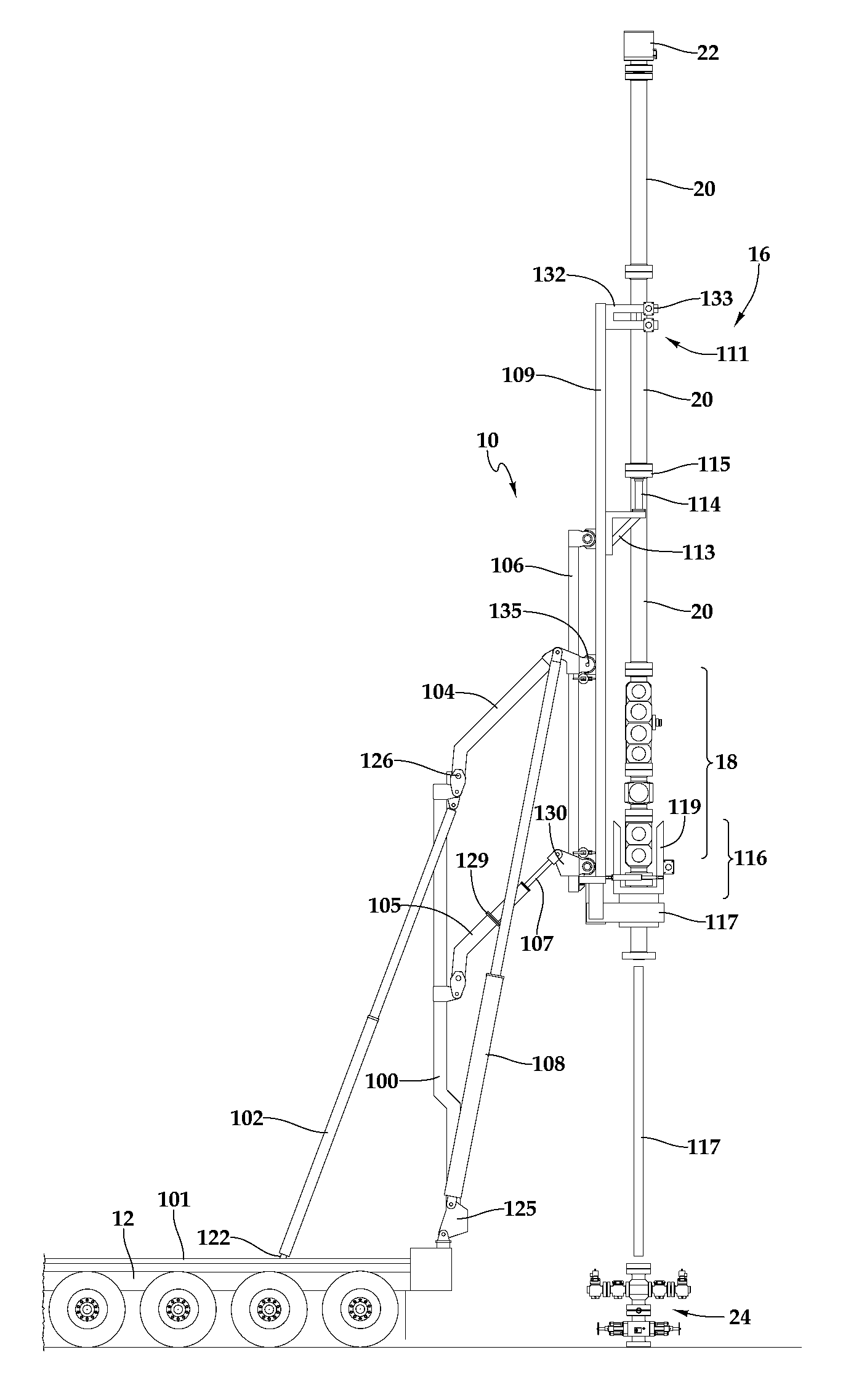
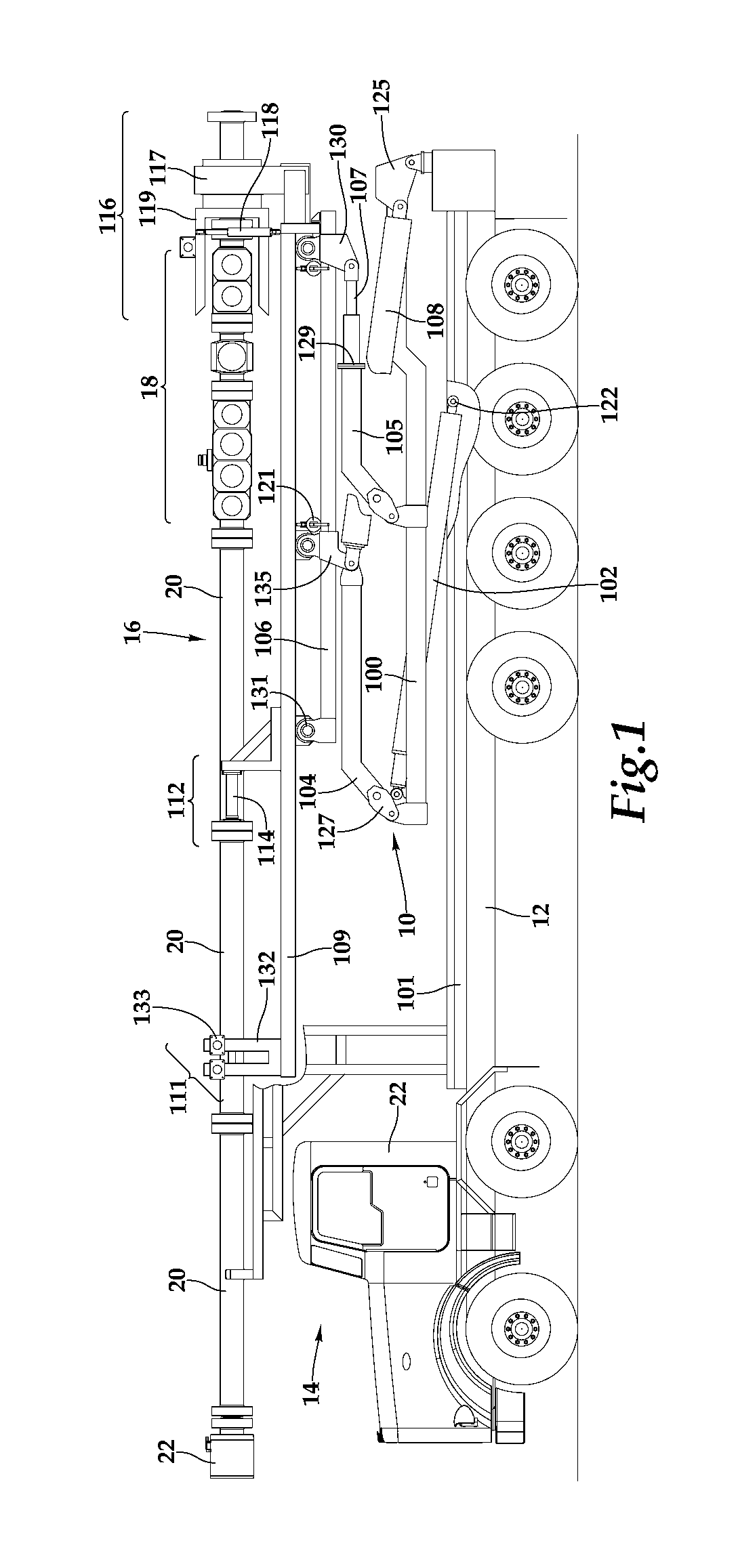
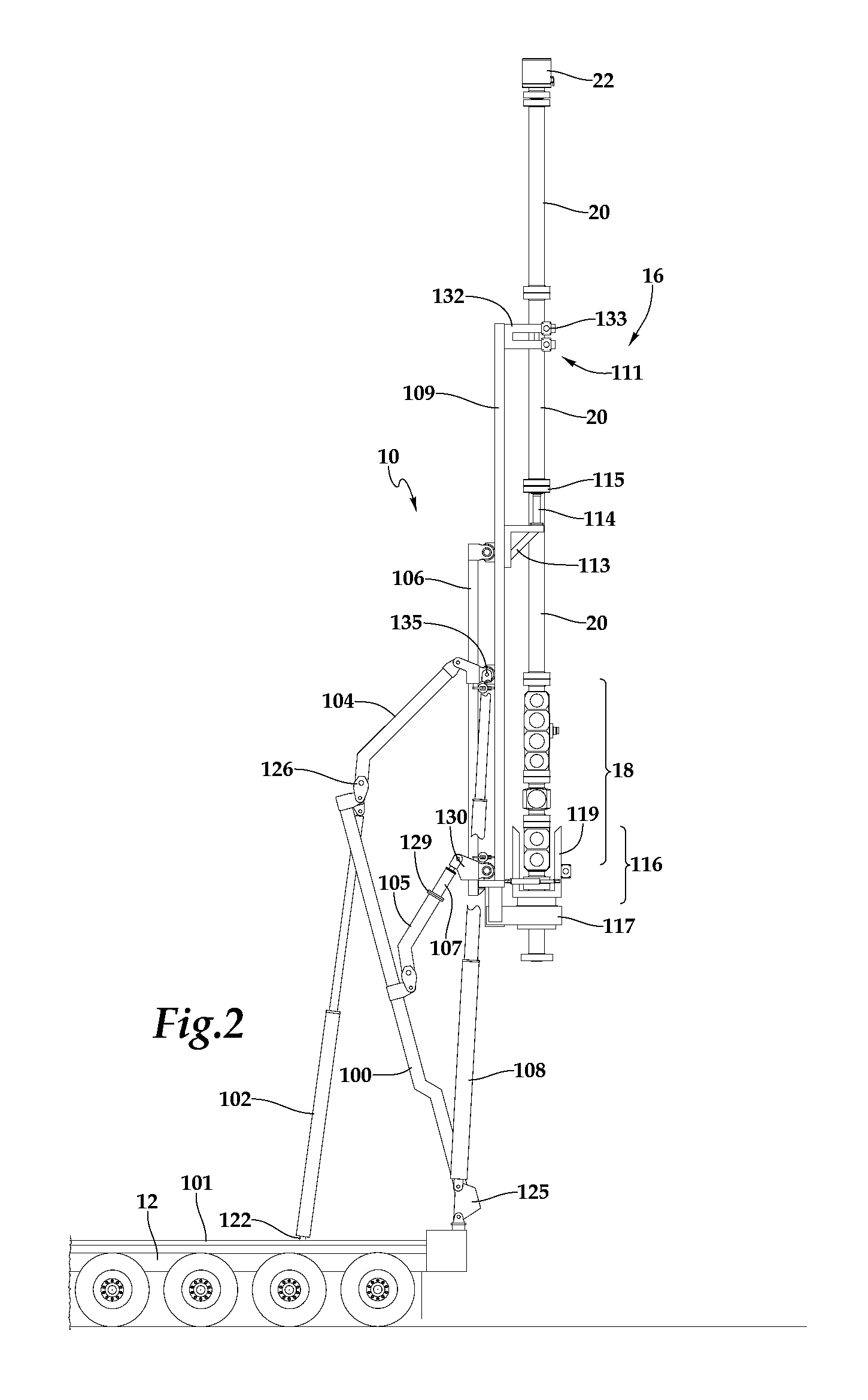
The patent describes a new handler for a BOP assembly that can hold and elevate the assembly for use in oil and gas wells. The handler is designed to provide a safer workspace and allows for easier alignment and connection to the injector and well head. The handler can be positioned over the well head and has the ability to move the BOP assembly in a vertical and rotational manner. This allows for easier and more efficient well drilling operations.

Problems solved by technology

Installing and connecting the tools to the tubing is tedious and time consuming, usually involving more than one person.

Method used


Image

  • Handler for blowout preventer assembly
  • Handler for blowout preventer assembly
  • Handler for blowout preventer assembly

Examples


Embodiment Construction

[0016]In the following description, like numbers refer to like elements.

[0017]A representative example of an embodiment of a BOP assembly handler is capable of stowing in a horizontal position a partially or fully assembled blow out preventer (BOP) assembly and then maneuvering it over a wellhead of an oil or gas well for attachment and, if desired, support. Such a handler comprises a linkage for maneuvering a support frame that carries the BOP assembly. The linkage is capable of not only standing the BOP assembly up, but also raising it vertically and moving it horizontally away from the base of the handler. It also, preferably, raises it high enough and far enough beyond the end of the base on which the handler is mounted, to allow for insertion of tools within the risers, and then also laterally over the wellhead, where it can be connected to wellhead. Once connected to the wellhead, it may be used to support the weight of the BOP assembly and, optionally, the coiled tubing injec...


PUM


Abstract

A handler holds a blowout preventer (BOP) assembly (partially or fully assembled) for transport and then erects it from a transport position to a vertical position for deployment. In the transport position the BOP assembly generally rests in a horizontal position. During deployment of the BOP assembly by the handler, the handler is capable of moving the BOP assembly to a vertical position, elevating it, and moving it outward, away from the base of the handler and toward a wellhead, so that the BOP assembly may be connected to a coiled tubing injector, work may be performed underneath the BOP assembly before connection to a well head, and the BOP assembly may be placed on top of a well head for connection to the well head.

Description

TECHNICAL FIELD OF THE INVENTION[0001]The invention pertains generally to handlers for positioning high pressure blow out preventer assemblies and the like above well heads in oilfield service operations.BACKGROUND[0002]Coiled steel tubing, or simply “coiled tubing,” is single string of steel pipe that is continuously milled and coiled onto a large take-up reel for transportation and handling. It can be run into and out of a well bore at a high rate, relative to straight, jointed pipe, and, unlike wire line, it can be pushed into the well bore. It has been manufactured in lengths greater than 30,000 feet. Useful in a wide range of oilfield services and operations, including drilling, it is more often used after the well is drilled for logging, cleanouts, fracturing, cementing, fishing, completion and production related operations.[0003]Coiled tubing is run in and out of well bores using a machine called a coiled tubing injector. The name “coiled tubing injector” derives from the fac...

Claims


Application Information

Patent Timeline
Patent Type & Authority Patents(United States)
IPC IPC(8): E21B33/06E21B19/00
CPCE21B33/06E21B19/00E21B33/068E21B19/22
Inventor LU, MIKE XIAOLEIMCCULLOCH, DAVID W.
Owner NAT OILWELL VARCO LP
Learn More