
Anti-collision component

a technology of anti-collision and component, which is applied in the direction of bumpers, vehicle components, doors, etc., can solve the problems of increasing the damage to the body, increasing the number of components and welding steps, and increasing the cost, so as to improve the designability and operability of the automobile, shorten the length of the web, and reduce the dimension

Active Publication Date: 2016-05-31
KOBE STEEL LTD +1
View PDF13 Cites 2 Cited by
  • Summary
  • Abstract
  • Description
  • Claims
  • Application Information

AI Technical Summary

Benefits of technology

The present invention relates to an anti-collision component such as a bumper reinforcement, which requires to have high deformation strength and also to reduce the outer shape dimension of each longitudinal end while maintaining its strength. However, traditional methods to achieve this require the use of a separate component to compensate for the strength degradation, which increases cost and weight. The present invention aims to address this issue by proposing an alternative solution. The invention proposes the use of a steel reinforcement profile with swaged ends, which improves designability and operability of the automobile and prevents strength degradation of the reinforcement without the need for a separate component. The invention also ensures the smooth flow of material in the corner or connecting portion, thereby preventing cracks and improving the collision resistant performance.

Problems solved by technology

Consequently, in a front collision with a small overlap amount, a collision article intrudes into the body to increase damage to the body.
In addition, to increase the deformation load in collision, a different member can be mounted to increase the strength of the end (see JP 2006-151095 A), but the increase in the number of components and the number of welding steps causes higher cost.
When a reinforcing component such as a bracket is made larger in order to compensate for the strength degradation, the cost and weight are increased.

Method used


Image

  • Anti-collision component
  • Anti-collision component
  • Anti-collision component

Examples


examples

[0056]To study the effect of the anti-collision component for automobiles according to the present invention, using the CAE (Computer Aided Engineering) analysis, deformation loads of the bumper reinforcements of the present invention example and the conventional example in front collision with a small overlap amount were calculated.

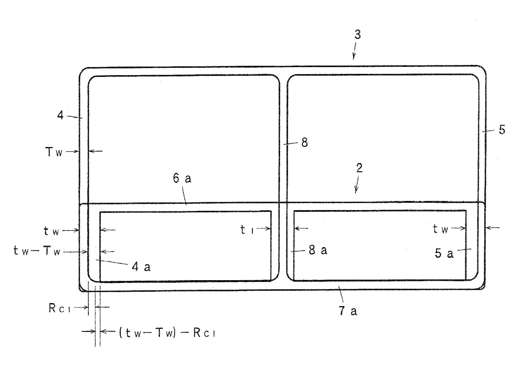
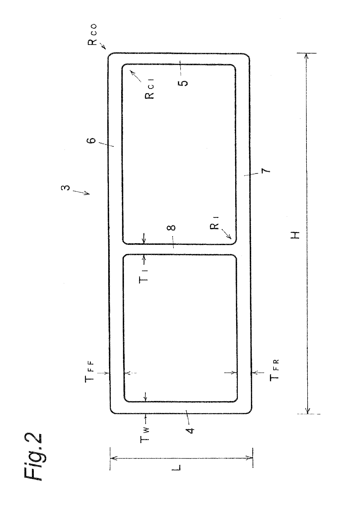
[0057]The metal hollow profile was made of the 7000-series aluminum extrusion, and had the cross-sectional configuration illustrated in FIG. 2. The metal hollow profile had an outer shape dimension of 40 mm×110 mm, body front-rear dimension L of 40 mm, and body heightwise dimension H of 110 mm. Wall thickness TW of each of the webs 4, 5 and wall thickness TI of the intermediate web 8 were 3.5 mm, wall thickness TFF of the collision side flange 6 was 4.0 mm, and wall thickness TFR of the automobile side flange 7 was 4.5 mm. Inside corner radius RCI of each of four corners formed by the webs 4, 5 and the flanges 6, 7 and fillet radius RI of each of four co...


PUM


Abstract

An anti-collision component consisting of a metal hollow profile for automobiles includes a collision side flange, a body side flange, and a web connected to the flanges. The hollow profile has a longitudinal end at which a cross-sectional configuration is deformed by swaging to reduce a dimension between the flanges. The following relations are established:tW>TW RCI≧(tW−TW)where tW is a wall thickness of the web at the end, TW is a wall thickness of the web at a portion where the cross-sectional configuration is not deformed, and RCI is an inside corner radius of a corner formed of the web and each flange at the portion.

Description

CROSS-REFERENCE TO RELATED APPLICATIONS[0001]This application claims priority of Japanese Patent Application No.: 2014-215429 filed on Oct. 22, 2015, the content of which is incorporated herein by reference.BACKGROUND OF THE INVENTION[0002]The present invention relates to an anti-collision component for automobiles, such as a bumper reinforcement, a door impact beam, a roof reinforcement, an FUP (front underrun protector) for a truck, and an RUP (rear underrun protector) for a truck.RELATED ART[0003]With the recent enforcement of the automobile collision standards, mounted are anti-collision components, such as a bumper reinforcement, a door impact beam, a roof reinforcement, an FUP, and an RUP, which are members against a front or rear collision with a small overlap amount (also called offset barrier collision or small lap collision), an oblique collision (also called end pendulum collision), and a side collision (also called side impact).[0004]These anti-collision components are r...

Claims


Application Information

Patent Timeline
Patent Type & Authority Patents(United States)
IPC IPC(8): B60R19/18B60R19/03
CPCB60R19/18B60R19/03B60R2019/186B60R19/023B60J5/0444B60R2019/182
Inventor ISHITOBI, HIDEKIHASHIMOTO, NARIKAZUTSUYOSHI, TSUNETAKESHIMOAKA, SHINGOOHTANI, TOMOMICHINAKAYA, KENJICHINO, KEI
Owner KOBE STEEL LTD
Learn More