
Gamma boosting unit (GBU) for hybrid load and source pull

a gamma boosting unit and source pull technology, applied in the field of gamma boosting units, can solve the problems of large mismatch situation, passive tuner cannot allow testing of dut's with internal impedances,

Active Publication Date: 2016-05-03
TSIRONIS CHRISTOS
View PDF2 Cites 13 Cited by
  • Summary
  • Abstract
  • Description
  • Claims
  • Application Information

AI Technical Summary

Benefits of technology

The patent text describes a method for testing and characterizing high power microwave amplifiers and oscillators used in communication systems. The method involves using load pull, which involves manipulating the impedance conditions under which the device operates. The text explains the two main methods for load pull: passive and active. The active method uses active tuners to generate and manipulate the impedance conditions, while the passive method uses electromechanical or passive electronic tuners. The text also describes a hybrid system that combines both passive and active tuners to allow for testing devices with lower internal impedance. The technical effect of this invention is to provide a more accurate and reliable method for testing and characterizing high power microwave amplifiers and oscillators.

Problems solved by technology

Considering unavoidable insertion loss between the DUT and the test port of a load pull tuner in a realistic test set-up, this means that a passive tuner can only allow testing of DUT's with internal impedances above roughly 2Ω.
Generating a large reflection coefficient with active tuner systems in combination with a high output power at the DUT reference plane requires an extremely high level of injected power, since available power amplifiers have a typical output impedance of 50Ω, whereas the DUT has <2Ω; this creates a large mismatch situation, which requires large power from the power amplifier.

Method used


Image

  • Gamma boosting unit (GBU) for hybrid load and source pull
  • Gamma boosting unit (GBU) for hybrid load and source pull
  • Gamma boosting unit (GBU) for hybrid load and source pull

Examples


Embodiment Construction

[0036]The proposed tuner system is a hybrid system, a combination of a passive and active tuner system. The invention is a closed loop system, which means the system is independent of the available power of the device under test (DUT).

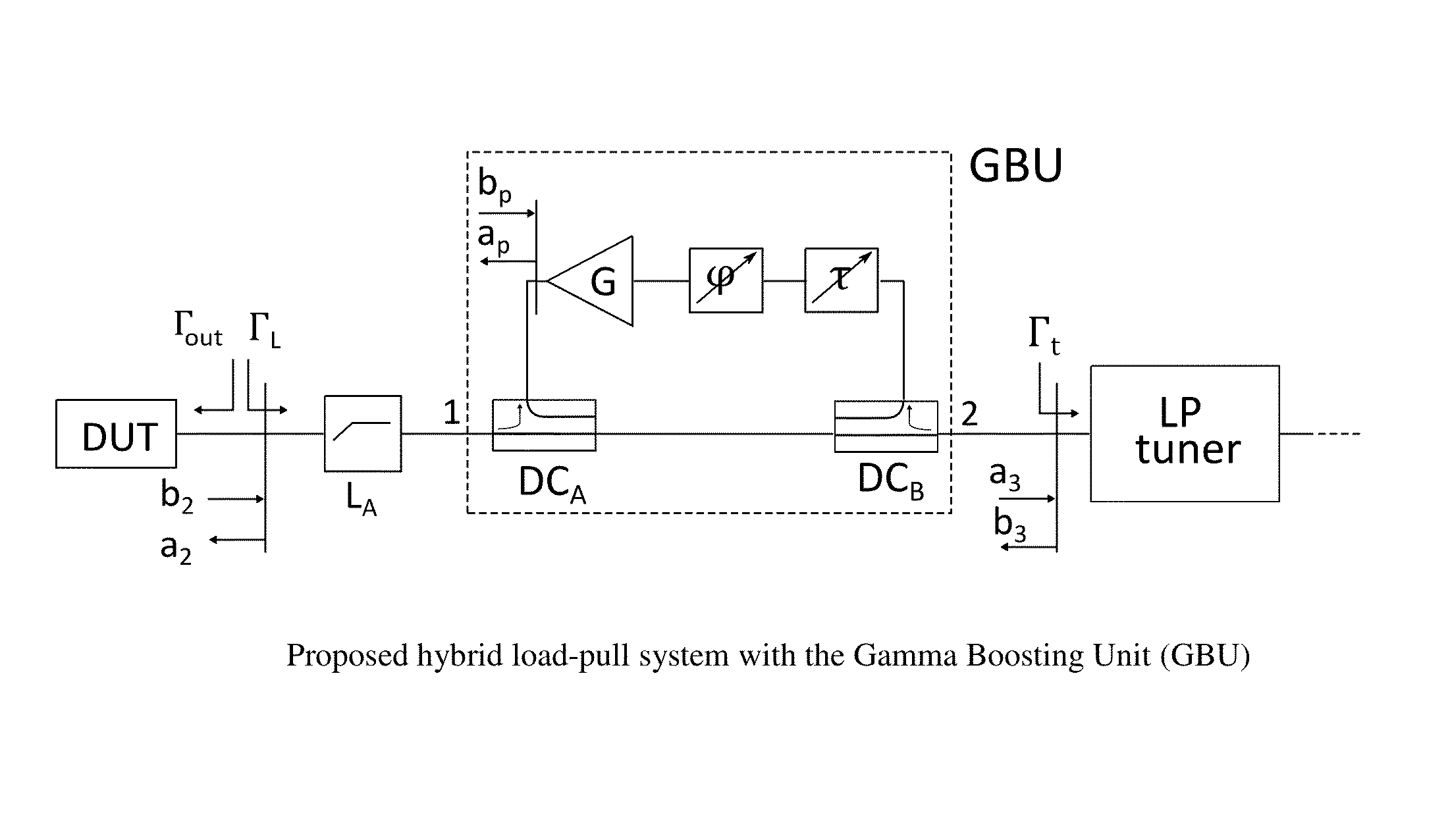
[0037]The proposed hybrid system is formed around a Gamma Boosting Unit (GBU) and is shown in FIG. 6. The GBU consists of two broadband directional couplers DCA and DCB, a broadband variable time-delay, broadband variable phase-shifter and a broadband microwave amplifier which has an available gain of G. The losses of the probe and cable are indicated as LA.

[0038]Assuming the components of the system (FIG. 6) (except “LP tuner”) are matched to 50Ω, the principle of the operation of the proposed system is as follows:

[0039]The outgoing power wave from the DUT's output, b2, flows through the through paths of DCA and DCB towards the passive tuner. Here some part of the wave will be reflected at the input-plane of the tuner to generate a new power wave, b3....


PUM


Abstract

A hybrid load pull tuner system uses a combination of a passive and active tuner system. A closed loop system means that the system is independent of the available power of the device under test (DUT). The proposed hybrid system is formed around a closed loop Gamma Boosting Unit (GBU) consisting of two back to back broadband directional couplers, broadband variable time-delay, broadband variable phase-shifter and a broadband microwave amplifier, all inserted in the coupled path of the couplers; the GBU is connected in cascade with a passive tuner and boosts its reflection factor; for this the amplifier must have enough linear power and gain to match the difference between the power reflected back to the DUT by the passive tuner and the desired total reflected power to reach the expected Gamma, considering coupling loss and insertion loss of the test fixture.

Description

PRIORITY CLAIM[0001]This application claims priority on provisional application 61 / 646,400 filed on May 14, 2012.CROSS-REFERENCE TO RELATED ARTICLES[0002][1] F. M. Ghannouchi, M. S. Hashmi, Load-Pull Techniques with Applications to Power Amplifier Design, Springer Series in Advanced Microelectronics 32 DOI 10.1007 / 978-94-007-4461-5_2, © Springer Science+Business Media Dordrecht 2013[0003][2] Active load pull: http: / / www.microwaves101.com / encyclopedia / loadpull.cfm[0004][3] Passive tuners, see [1]BACKGROUND OF THE INVENTIONPrior Art[0005]Modern design of high power microwave amplifiers and oscillators, used in various communication systems, requires accurate knowledge of the active device's (microwave transistor's) characteristics. A popular method for testing and characterizing such microwave components (transistors) in the non-linear region of operation is “load pull”. Load pull is a measurement technique employing microwave tuners and other microwave test equipment. The microwave t...

Claims


Application Information

Patent Timeline
IPC IPC(8): H03J1/00
CPCH03J1/00G01R31/2608G01R31/2614G01R31/2822
Inventor MAHMOUDI, REZAMALEKZADEH, FOAD ARFAEIESSING, JACOBUS A. J.
Owner TSIRONIS CHRISTOS
Learn More