
Surgically implantable joint spacer

a surgically implanted, joint technology, applied in the field of medical implants, can solve the problems of multiple problems of individuals or animals, degraded biologic joints, sporadic or constant pain,

Active Publication Date: 2016-04-26
RODRIGUEZ CARLOS ANDRES +1
View PDF43 Cites 3 Cited by
  • Summary
  • Abstract
  • Description
  • Claims
  • Application Information

AI Technical Summary

Benefits of technology

The patent text describes a process for straightening a spinal implant by reducing the temperature of a spacer member to a level that prevents it from transforming. This can be beneficial in non-joint medical applications where the shape of the implant is important. Examples include using the implant to help heal fractures, reshaping curved regions, or replacing a nasal implant. The technical effect of this involves improving the stability and integrity of the implant during the straightening process.

Problems solved by technology

Biological joints can degrade over time, deteriorate as a result of a birth defect or a disease, become damaged as a result of an accident or unwarranted motion, malformations due to incorrect growths, and the like.
As the joint deviates from a normal, mobile condition, the malformed joint can cause multiple issues to the individual or animal, including sporadic or constant pain, limited motion, any degree of incapacitation, and the like.
Inter-vertebrae discs can degrade over time or become damaged where they no longer function properly.
The defective inter-vertebrae discs limit or reduce the support along the individual's spine.
One short-term drawback of this procedure is the resulting limitation of motion incurred by the individual.
A long-term drawback is that over time, the fused region increases stresses on adjacent joints, resulting in additional surgical procedures to fuse other regions of the individual's spine.
As either or both of the surfaces of the joint members wears or deteriorates, the support of the joint degrades, hindering the mobility of the individual.
In addition to the reduced mobility, the deteriorating joint can cause inflammation, discomfort, and other unwanted physical and psychological issues.

Method used


Image

  • Surgically implantable joint spacer
  • Surgically implantable joint spacer
  • Surgically implantable joint spacer

Examples


Embodiment Construction

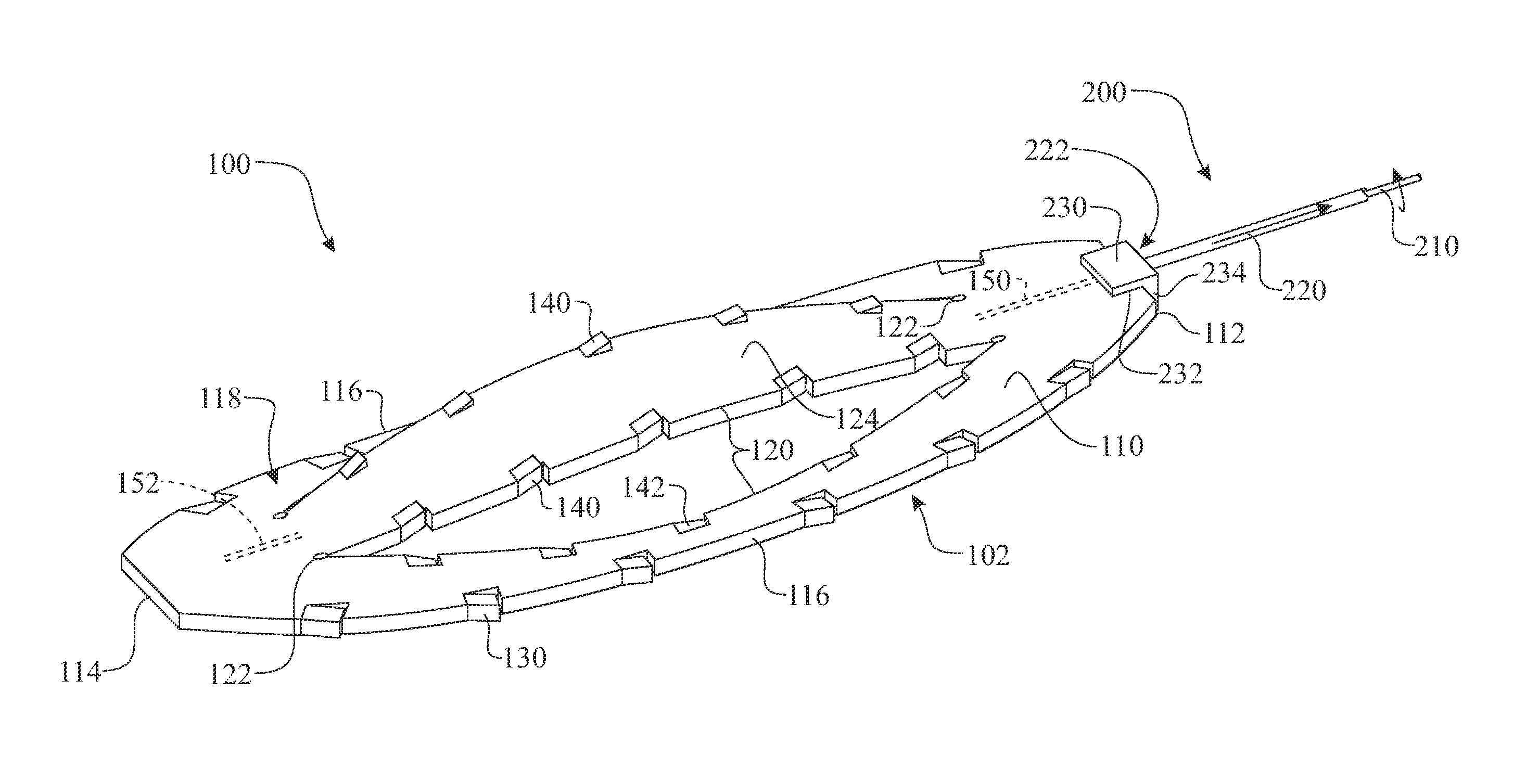
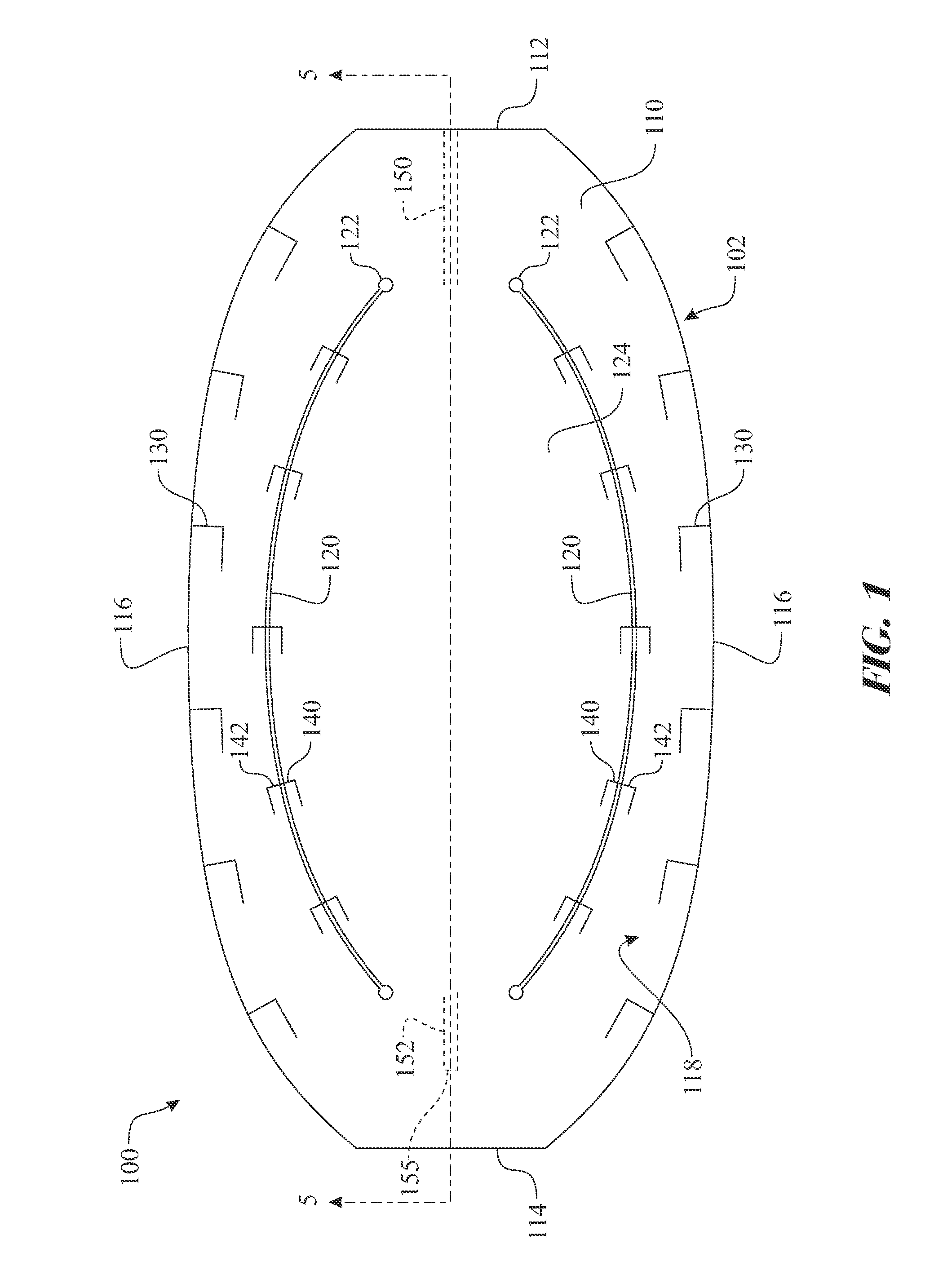
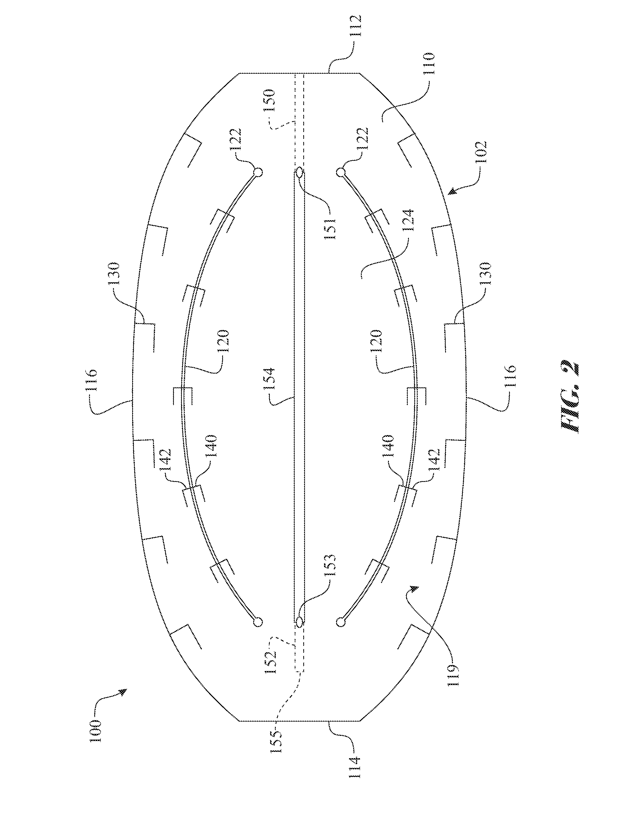
[0073]The following detailed description is merely exemplary in nature and is not intended to limit the described embodiments or the application and uses of the described embodiments. As used herein, the word “exemplary” or “illustrative” means “serving as an example, instance, or illustration.” Any implementation described herein as“exemplary” or “illustrative” is not necessarily to be construed as preferred or advantageous over other implementations. All of the implementations described below are exemplary implementations provided to enable persons skilled in the art to make or use the embodiments of the disclosure and are not intended to limit the scope of the disclosure, which is defined by the claims. For purposes of description herein, the terms “upper”, “lower”, “left”, “rear”, “right”, “front”, “vertical”, “horizontal”, and derivatives thereof shall relate to the invention as oriented in FIG. 1. Furthermore, there is no intention to be bound by any expressed or implied theor...


PUM


Abstract

A spacer formed of an intermetallic compound, such as nitinol. The spacer includes two segments shaped in opposing arches. The unique properties of the intermetallic compound enable the material to be deformed into a planar, insertable shape when the material is cooled below a transition temperature and returns to the undeformed shape when the material returns to an ambient, operational temperature. An expansion mechanism assembly can engage with the spacer to apply an expansion force. The expansion force extends the spacer longitudinally drawing the spacer into the planar configuration. The expansion mechanism assembly can be used to guide the spacer into the desired position within the patient. The spacer control mechanism assembly is subsequently removed, relieving the expansion force. The spacer returns to the natural undeformed shape as it returns to body temperature. Retention features can be integrated in the spacer to aid in retaining the spacer in location.

Description

CROSS-REFERENCE TO RELATED APPLICATION[0001]This Non-Provisional Utility application claims the benefit of U.S. Provisional Patent Application Ser. No. 61 / 716,534, filed on Nov. 15, 2012, which is incorporated herein in its entirety.FIELD OF THE INVENTION[0002]The present disclosure generally relates to a medically implanted spacer. More particularly, the present disclosure relates to a medically implanted spacer for insertion within a joint formed between two adjacent bones to enhance movement or fuse in a deteriorated biological joint.BACKGROUND OF THE INVENTION[0003]Biological joints can degrade over time, deteriorate as a result of a birth defect or a disease, become damaged as a result of an accident or unwarranted motion, malformations due to incorrect growths, and the like. As the joint deviates from a normal, mobile condition, the malformed joint can cause multiple issues to the individual or animal, including sporadic or constant pain, limited motion, any degree of incapaci...

Claims


Application Information

Patent Timeline
Patent Type & Authority Patents(United States)
IPC IPC(8): A61F2/30A61F2/44A61F2/46
CPCA61F2/442A61F2/4465A61F2/4611A61F2002/30092A61F2002/30125A61F2002/30556A61F2002/30579A61F2002/30777A61F2002/30797
Inventor RODRIGUEZ, CARLOS ANDRESRODRIGUEZ, CIRA
Owner RODRIGUEZ CARLOS ANDRES
Learn More