
Combine harvester comprising a chopping mechanism

a technology of chopping mechanism and combine harvester, which is applied in the direction of mowers, agricultural tools and machines, and mowers, can solve the problems of high complexity of the drive form of the spreading mechanism, achieve the effect of reducing the drive speed of the chopping mechanism, improving the adaptation to changing harvesting conditions, and facilitating speed adjustmen

Active Publication Date: 2016-04-19
CLAAS SELBSTFAHRENDE ERNTEMASCHINEN GMBH
View PDF8 Cites 3 Cited by
  • Summary
  • Abstract
  • Description
  • Claims
  • Application Information

AI Technical Summary

Benefits of technology

[0005]To that end, the present invention provides a combine harvester characterized by a simple and energy-efficient drive of the spreading mechanism thereof.
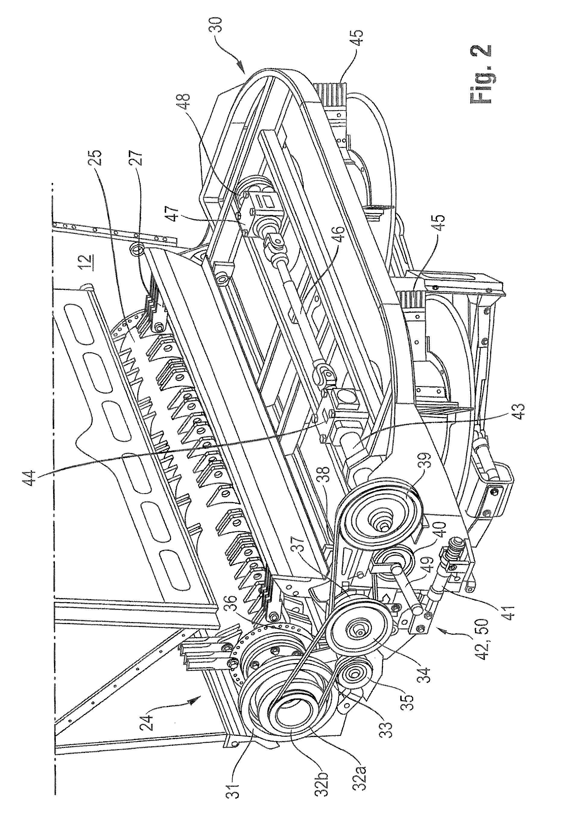
[0007]The mechanical drive of the spreading mechanism has the advantage over a hydraulic drive that the mechanical drive is characterized by the speed stability thereof, which results in greater stability of distribution. In light of safety requirements on the operation of spreading mechanisms, the rotors of which are disposed in an at least partially exposed manner, it is necessary to avoid long run-on times resulting from inertia. A clutch and a brake are therefore integrated in the drive train and disengage said drive train in order to decouple the drive train of the spreading mechanism from the combine harvester and actively brake the rotors. Rapid braking of the spreading mechanism and the rotors is thereby achieved.
[0009]Preferably, the belt drive is driven by a step drive. Given that the belt wraps from a pulley having a relatively large diameter onto a pulley having a relatively small diameter, speed adjustment can be easily implemented. This is significant when processing crop such as corn, for example, which, due to the properties thereof, requires a lower drive speed of the chopping mechanism although the spreading width remains unchanged, and therefore the drive speed of the spreading mechanism must be substantially higher than that of the chopping mechanism. An appropriate gear ratio can be implemented by the step drive.
[0010]As an alternative, the belt drive is driven by a variator. The variator permits stepless adjustment of the drive speed of the spreading mechanism, thereby improving the adaptation to changing harvesting conditions. The belt drive is used as a clutch in particular. The drive train is interruptible by the belt drive, which is used as a clutch, when the intention is to idle the chopping mechanism and the spreading mechanism. The use of the belt drive as a clutch is a cost-effective solution, since additional components in the drive train can be omitted.

Problems solved by technology

This form of the drive for a spreading mechanism is characterized by high complexity.

Method used


Image

  • Combine harvester comprising a chopping mechanism
  • Combine harvester comprising a chopping mechanism
  • Combine harvester comprising a chopping mechanism

Examples


Embodiment Construction

[0022]The following is a detailed description of example embodiments of the invention depicted in the accompanying drawings. The example embodiments are presented in such detail as to clearly communicate the invention and are designed to make such embodiments obvious to a person of ordinary skill in the art. However, the amount of detail offered is not intended to limit the anticipated variations of embodiments; on the contrary, the intention is to cover all modifications, equivalents, and alternatives falling within the spirit and scope of the present invention, as defined by the appended claims.

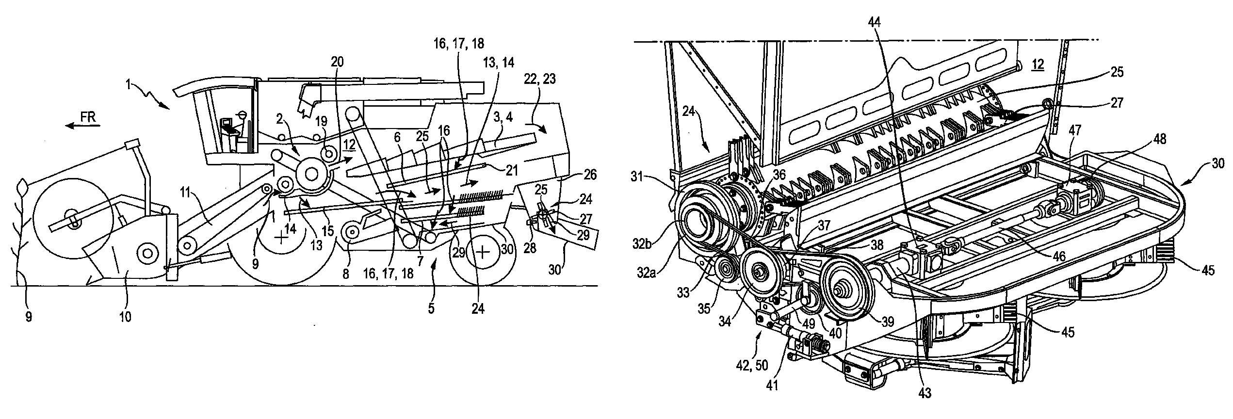
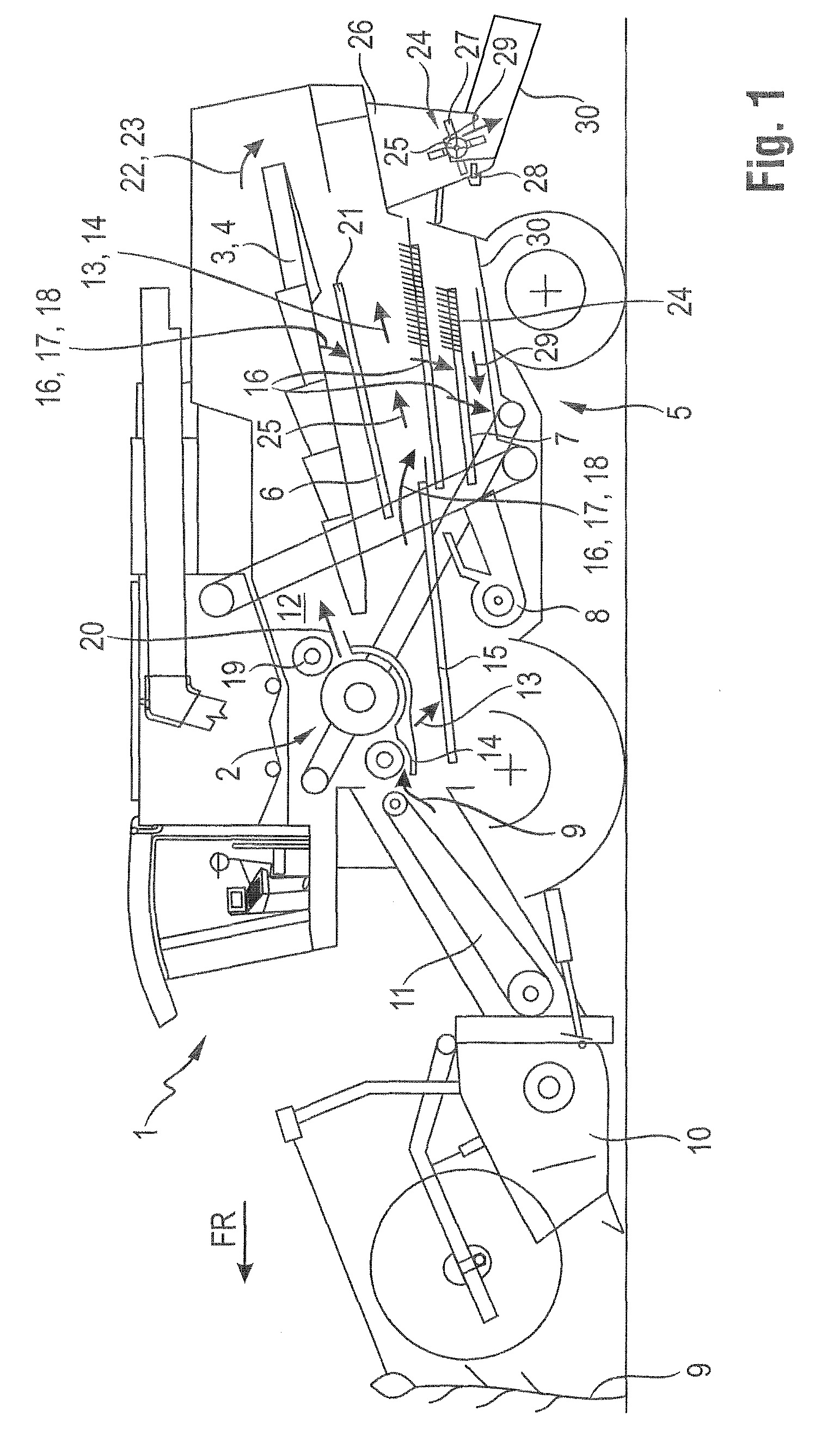
[0023]FIG. 1 depicts a side view of a harvesting machine designed as a combine harvester 1, comprising a threshing mechanism 2, which is known per se and is therefore not described in greater detail, and a downstream tray-type shaker 3, as the separating device 4. A cleaning mechanism 5 is disposed underneath the tray-type shaker 3 and comprises two sieves 6, 7, which are disposed one above...


PUM


Abstract

A combine harvester has a chopping mechanism and a spreading mechanism. The spreading mechanism is disposed downstream of the chopping mechanism, mechanically driven by a drive train and includes at least two rotors. The drive train of the spreading mechanism has a belt drive engageable by a clutch and configured to drive a first transmission stage via an output shaft, at least one second transmission stage drivably connected to the first transmission stage by a shaft and a braking device. The first and second transmission stages each have an output shaft for driving one or each of the rotors.

Description

CROSS-REFERENCE TO A RELATED APPLICATION[0001]The invention described and claimed hereinbelow is also described in German Patent Application DE 10 2013 108923.2, filed on Aug. 19, 2013. The German Patent Application, the subject matters of which is incorporated herein by reference, provides the basis for a claim of priority of invention under 35 U.S.C. 119(a)-(d).BACKGROUND OF THE INVENTION[0002]The present invention relates to a combine harvester comprising a chopping mechanism and a spreading mechanism which is disposed downstream thereof.[0003]Document DE 197 50 393 A1 makes known a mechanical drive for a chaff spreader, which is disposed downstream of a cleaning mechanism and comprises two or more fan units that are mechanically driven. To this end, a V-belt pulley is disposed on a shaft in a freely rotatable manner that is connectable in a non-positive manner to the V-belt pulley by a clutch. The V-belt pulley is driven via a drive train of the combine harvester, although this ...

Claims


Application Information

Patent Timeline
Patent Type & Authority Patents(United States)
IPC IPC(8): A01D41/12
CPCA01D41/1243
Inventor KNIERBEIN, CLAUDIUSTEROERDE, STEFANSTRIEKER, NORBERTVIEREGGE, CHRISTOPHERSCHIEWER, STEFAN
Owner CLAAS SELBSTFAHRENDE ERNTEMASCHINEN GMBH
Learn More