
Apparatus and method for locating, tracking, controlling and recognizing tagged objects using active RFID technology

a technology of active radio frequency identification and apparatus, applied in the field of intermittently active radio frequency identification (rfid) tags, can solve the problems of limitations of the prior, drawbacks of conventional rfid, and inability to detect objects, and achieve the effect of convenient operation

Inactive Publication Date: 2016-04-12
ROBINETTE JAMIE +1
View PDF17 Cites 39 Cited by
  • Summary
  • Abstract
  • Description
  • Claims
  • Application Information

AI Technical Summary

Benefits of technology

The system provides a cost-effective, reliable, and versatile solution for locating and tracking objects, offering scalable security and control functions, suitable for various applications from personal use to commercial and military needs, without the need for expensive infrastructure or complex technology.

Problems solved by technology

There is a need to overcome the limitations of the prior art and the drawbacks of conventional RFID, which remains expensive, complex, bulky and inconsistent in results.
Currently, only buttons on the wall or cumbersome remote controls can do this.
There is no device that allows a user to locate objects, like glasses, keys or pets, using inexpensive technology, active RFID tags and a portable controller small enough to be integrated for convenience into a finger ring, bracelet, fob, or other wearable object.

Method used


Image

  • Apparatus and method for locating, tracking, controlling and recognizing tagged objects using active RFID technology
  • Apparatus and method for locating, tracking, controlling and recognizing tagged objects using active RFID technology
  • Apparatus and method for locating, tracking, controlling and recognizing tagged objects using active RFID technology

Examples


embodiments

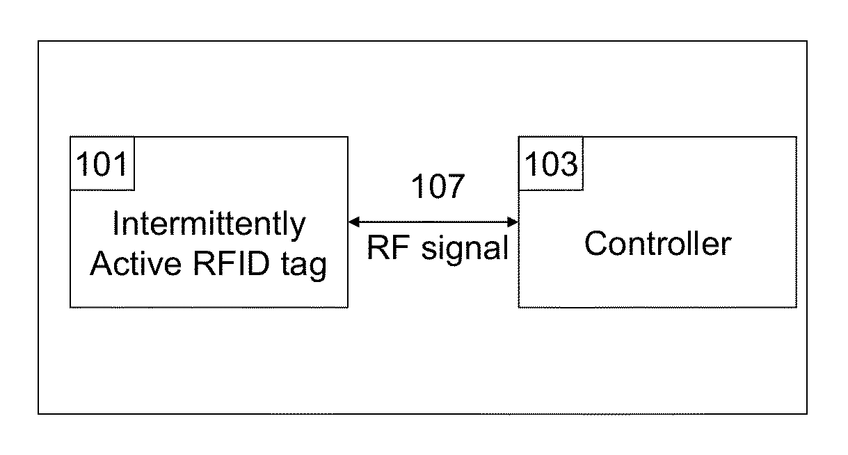
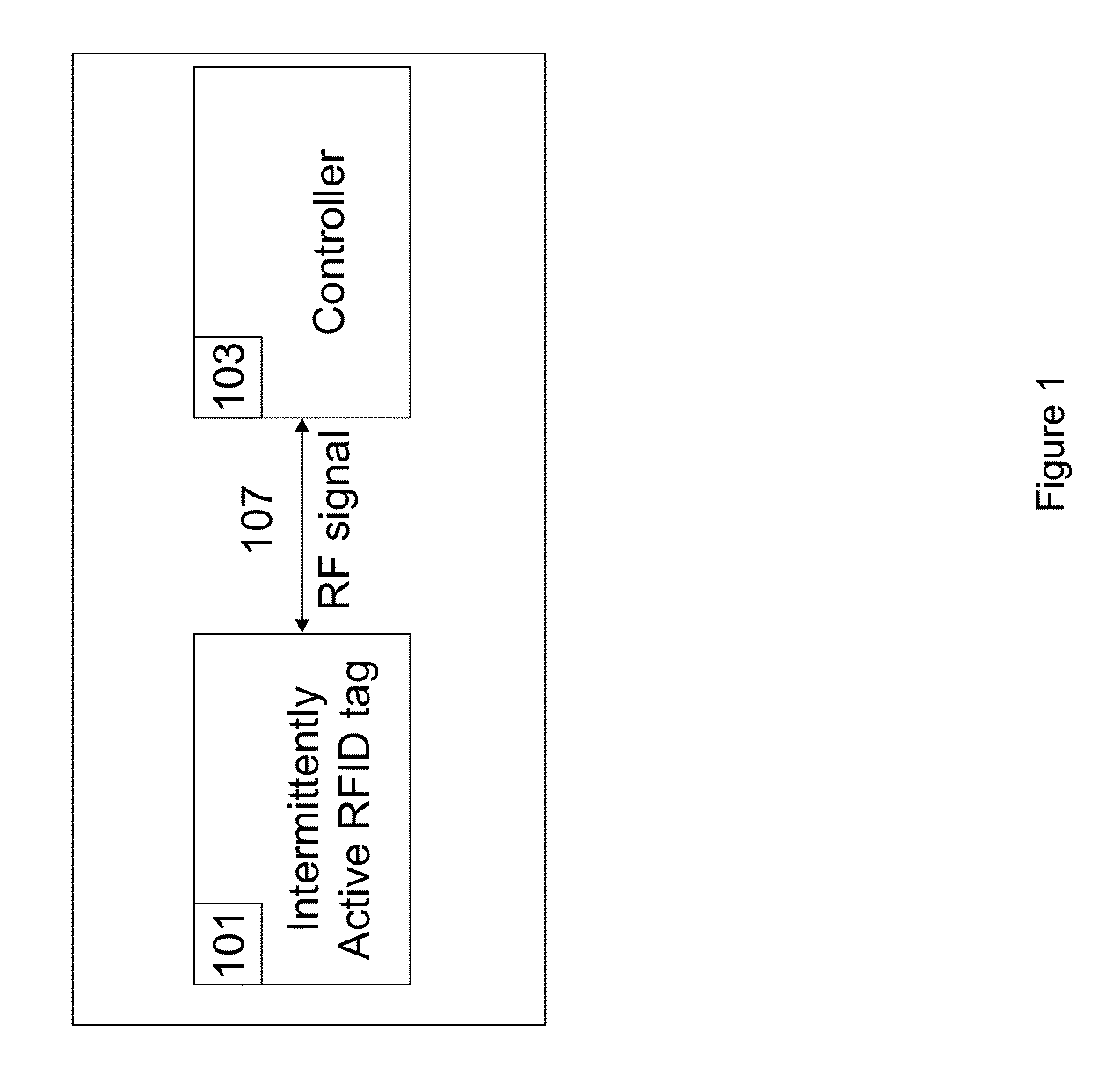
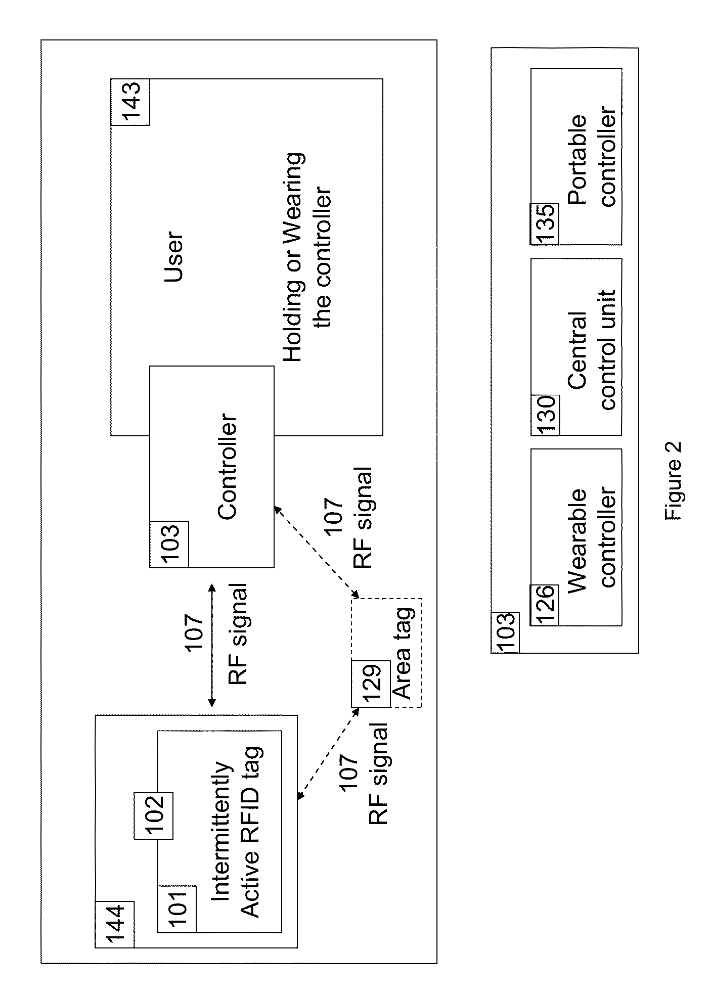
[0104]Controller: There are small wearable controllers 126, portable fob-like controllers 135, and central control unit controllers 130. The latter can configure the complete system by user input to its buttons or from a connected computer. All controllers consist of the hardware of the circuit 100 with microprocessor 108 and memory 120, an antenna 111, a power source 116, has input 121 and output 139. For 126 and 135, excluding the input / output mechanisms, the circuit is fully integrated into a housing 123 the user can wear, hold, or carry. The user can control other devices in the system by pushing a button or have other devices be controlled by the controller automatically. Control actions include tracking, switching on / off, lock / unlock, or report proximity to other devices.

[0105]Tag: The tag 101 consists of the hardware of the circuit 100 with microprocessor 108 and memory 120, antenna 111, a power source 116 and has one input of 104 / 105 / 132, and output 139. The circuit is fully...

example 1

Insider Threats

[0216]In the case of a rogue insider, the present invention has barriers to prevent data theft, even by highly skilled rogues. One feature is the autonomy of the present invention from an organization's IT department (hereinafter, “IT”). IT does not have control over this system, nor does it have an exemption; like everyone else, IT personnel are issued authorized USBs and not allowed to use personal devices. Their USBs and computers are linked to each other and to each employee's smart ID badge. There is a trend toward “BYOD” (Bring Your Own Device) to the work place and an opposite trend allowing employees to take laptops home; both pose enormous security risks, many of which are beyond the scope of the present invention, which can only enforce policies, not create them. The human factor is at the root of the mingling of personal matters and work. While there may be ways for the present invention to mitigate some of the risks, such as locating or tracking these devi...

example / embodiment

Example / Embodiment / Variation 4

Locks

[0227]Even very small amounts of critical data are taken for granted but at great risk. Vehicle entry systems, such as Remote Keyless Entry (RKE) and Passive Keyless Entry and Start (PKES) systems are ubiquitous for vehicles and moving into other applications, such as locks on a door. Unfortunately, these systems are vulnerable to attack.

[0228]With an active key, pressing a button opens the car and the metal key starts the car. The key must be relatively close (<100 m) and sends a one-way message to the car. The weakness is that the key and the car share the encryption key, but that cryptography is weak. The same is true of keys with immobilizer chips, which use passive RFID and require very close proximity, within centimeters. The remote opens the car and shares the cryptographic key with the vehicle, so here too there is a vulnerability of weak cryptography.

[0229]Passive Keyless Entry and Start (PKES) systems require the device to be within 2 to ...


PUM


Abstract

A real-time automated data security system protects both data and devices from loss, theft, and unauthorized access or activity. A miniature active RFID circuit is embodied in tags, area tags, controllers, USB sticks and a universal interface software for computers (i.e., Java), smart phones, and gateway boxes written to interface with the system. These devices are customizable and can link in arrays to cover large areas, use sensors, and scale up in module configurations to meet any need. The system is independent of electricity, GPS, satellites, the Internet, other software, and IT personnel. Its novel software, inside the tags, area tags and controllers is inaccessible and cannot be copied. Wireless transmissions are encrypted to military grade levels and packets are never repeated, making it unhackable, even by brute force attack. A unique battery-conserving protocol ensures good range and long battery life. The system has the ability to ignore copied packages or relaying by attackers, and to prevent of unauthorized access to USB sticks by proximity checks to the active RFID circuit.

Description

CROSS RELATION TO OTHER APPLICATIONS[0001]This is a continuation-in-part of U.S. application Ser. No. 13 / 064,378 filed Mar. 22, 2011, now U.S. Pat. No. 8,717,165, issued on May 6, 2014. The contents of said U.S. application Ser. No. 13 / 064,378, now U.S. Pat. No. 8,717,165, in its entirety, is hereby incorporated herein by reference.BACKGROUND OF THE INVENTION[0002]1. Field of the Invention[0003]The present invention relates to intermittently active radio frequency identification (RFID) tags to locate, track, control, and recognize animate or inanimate objects.[0004]Definitions: As used herein, the following terms have the following meanings, unless otherwise specified:[0005]RFID: radio frequency identification[0006]Tag: an active miniature RFID tag[0007]Controller: a portable controller, a wearable controller, a central control unit[0008]Signal: beep, chirp, light etc., mechanical, display with arrow or symbol, silent (stealth) logged and sent wirelessly later or sent wirelessly dir...

Claims


Application Information

Patent Timeline
Patent Type & Authority Patents(United States)
IPC IPC(8): G05B19/00G07C9/00G06K7/10G06K19/077G08B21/02G06K19/07G08B13/14G08B25/01G08B13/24
CPCG06K19/0705G06K7/10237G06K19/071G06K19/0711G06K19/07762G07C9/00103G07C9/00111G08B13/1427G08B21/0219G08B21/0255G08B21/0275G08B13/2417G08B25/016G07C9/27G07C9/28
Inventor ROBINETTE, JAMIEGERNANDT, TASSILO
Owner ROBINETTE JAMIE
Learn More