Optical amplifier arrangement

a technology of optical amplifiers and arrangement, which is applied in the direction of instruments, active medium shape and construction, lasers, etc., can solve the problems of inability to achieve combination, inability to easily adjust to an optimal frequency for a specific process, and insufficient input power, etc., to achieve the effect of folding the telescope, reducing the frequency, and compact arrangemen

Active Publication Date: 2016-04-05
LUXINAR LTD
View PDF13 Cites 0 Cited by
  • Summary
  • Abstract
  • Description
  • Claims
  • Application Information

AI Technical Summary

Benefits of technology

[0015]By providing an arrangement where the beam passes through the amplification medium along a first pre-amplification path, returns along the same first path and then passes through the amplification medium again along a second power amplification path which locally overlaps the pre-amplification path so that some partial coupling occurs, the system can ensure effective saturation of all the traverses through the amplifier. In addition, by passing the beam over the first pre-amplification path twice, efficient power extraction is achieved. As the second path differs from the first path, maximised overlap of the paths with the amplification medium can be achieved thus enabling amplification of low power ultra-short pulses to optimal power levels.
[0022]In an embodiment, the optical amplifier includes a pulse picker arranged at an input to the optical amplifier. In this way, pulses can be rejected from the input beam of the oscillator to lower the frequency and thereby lower the average input power. Thus frequency optimisation can be achieved for a specific average power.

Problems solved by technology

However, the processing speeds enabling mass manufacture require pulse repetition frequencies of between 100 kHz to 10 MHz, adjustable to an optimal frequency with average powers in excess of 100 W. Typically, such combinations are not achievable with most laser architectures as the maximum pulse energy is limited by non-linear effects and damage to the laser crystal.
Thin disk laser oscillators have achieved powers approaching 150 W, being at the lower end of the power range required, but at fixed pulse repetition frequencies of between 3.50 MHz and 60 MHz, being above the required range, and they cannot easily be adjusted to an optimal frequency for a specific process whilst maintaining the average power.
A disadvantage of this arrangement is that sufficient input power is required to ensure effective saturation occurs in the initial few passes through the amplifier.
In addition, a cascaded arrangement requires considerable space.
A disadvantage of this arrangement is in the requirement for active components.
Such Pockels cells and photoacoustic elements add cost and complexity to the arrangement.

Method used


Image

  • Optical amplifier arrangement
  • Optical amplifier arrangement
  • Optical amplifier arrangement

Examples


Embodiment Construction

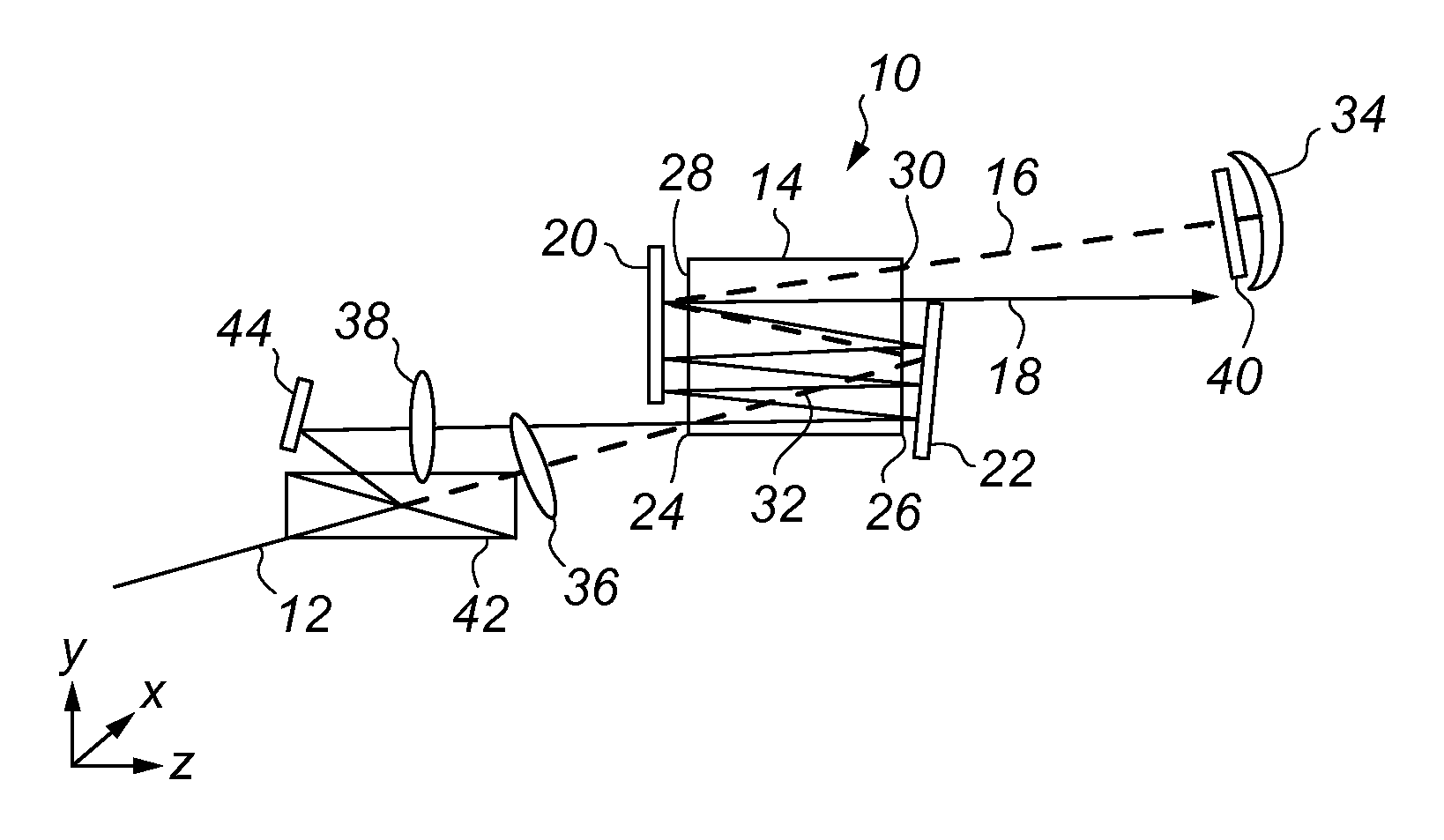
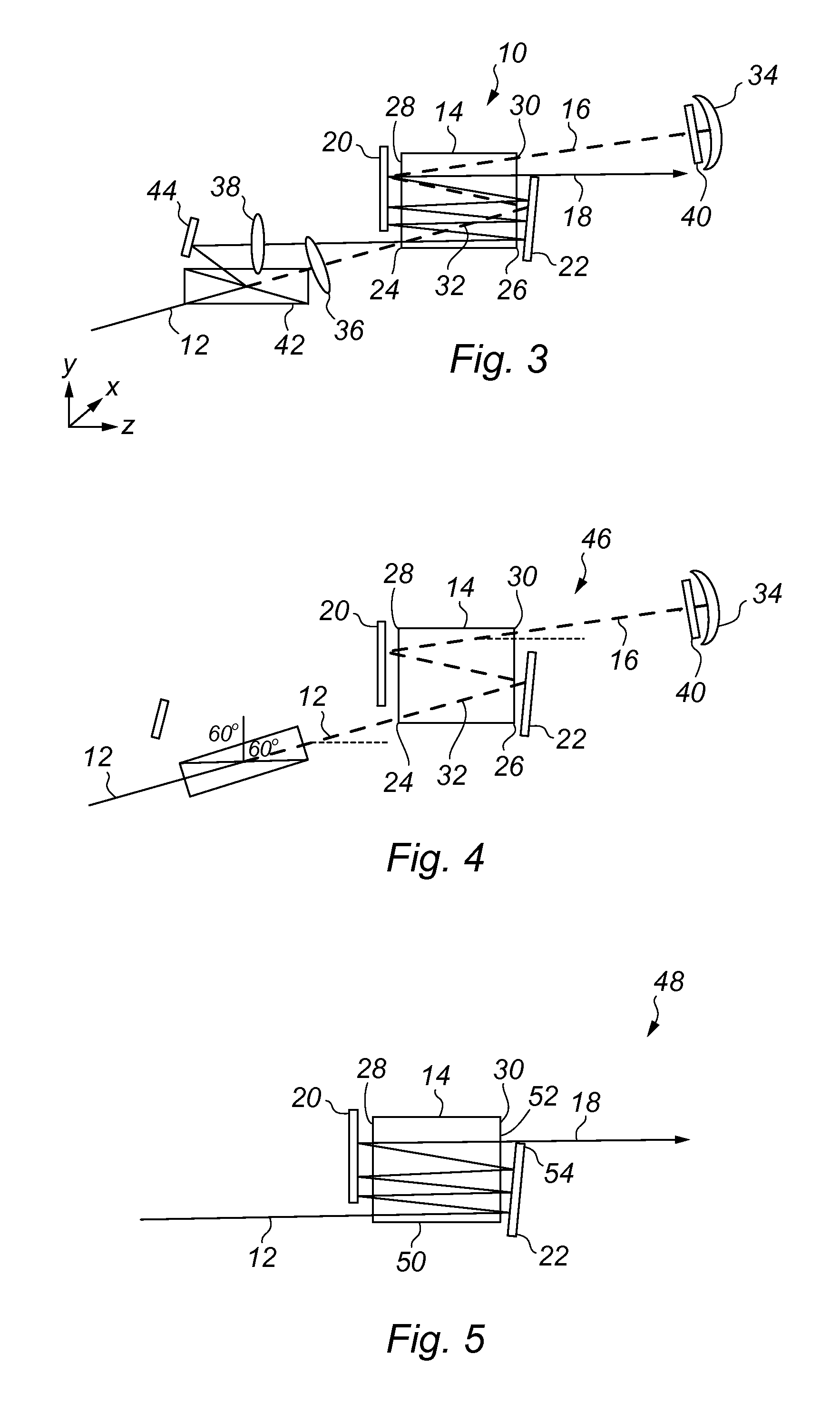
[0034]Reference is initially made to FIG. 3 of the drawings which illustrates an optical amplifier, generally indicated by reference numeral 10, where a beam 12, emitted from a low power, CW or pulsed, oscillator (not shown) is amplified by passing through an amplification medium 14 in a first path 16, which makes a double pass through the amplification medium 14, and a second path 18, which makes a single pass through the amplification medium 14, according to an embodiment of the present invention. On each path, the beam 12 traverses the amplification medium 14 multiple times by reflection from mirrors 20, 22 arranged on an entry side 24 and an opposing exit side 26 of the amplification medium 14, respectively.

[0035]Amplification medium 14 is a single crystalline slab being rectangular in cross-section with a short edge and a long edge. The short edge of the cross-section is along the x-axis, the long edge is along the y-axis, and the z-axis is the optical axis when the x-, y- and ...


PUM


Abstract

An optical amplifier which integrates a pre-amplifier and a power amplifier in a single rectangular active medium to enable amplification of low power ultra-short pulses to optimal power levels. A seed beam passes through the amplification medium along a first pre-amplification path making multiple traverses of the medium. It is imaged back along the first path to make a double pass of the medium as a pre-amplifier. The beam is then re-imaged into the medium again on a second power amplification path, making multiple traverses of the medium in a single pass. The paths are independent but overlap so that efficient power extraction is achieved. Embodiments based on all passive components are described.

Description

CROSS REFERENCE TO RELATED APPLICATIONS[0001]This United States application claims priority to GB1314098.3, filed 7 Aug. 2013.STATEMENT REGARDING FEDERALLY SPONSORED RESEARCH OR DEVELOPMENT[0002]Not applicable.BACKGROUND OF THE INVENTION[0003]The present invention relates to an optical amplifier apparatus for use in amplifying low power, reduced frequency, ultrashort pulse seeds and in particular, though not exclusively, to an optical amplifier apparatus having an integrated pre-amplifier and power amplifier in a single crystalline slab active region.[0004]Lasers with pulse widths of less than 10 ps offer new processing capabilities in micro-machining industrial applications. However, the processing speeds enabling mass manufacture require pulse repetition frequencies of between 100 kHz to 10 MHz, adjustable to an optimal frequency with average powers in excess of 100 W. Typically, such combinations are not achievable with most laser architectures as the maximum pulse energy is limi...

Claims


Application Information

Patent Timeline
Patent Type & Authority Patents(United States)
IPC IPC(8): H01S3/00H01S3/23H01S3/10H01S3/16H01S3/06H01S3/223H01S3/081H01S3/08H01S3/0941
CPCH01S3/10023H01S3/0602H01S3/163H01S3/2325H01S3/0606H01S3/0612H01S3/081H01S3/08072H01S3/08095H01S3/0941H01S3/10061H01S3/2232H01S3/2333H01S3/076H01S3/2375G02B26/02H01S3/23
Inventor LEE, JASON ROBERTFULFORD, BENJAMIN STUART
Owner LUXINAR LTD
Why Eureka
Try Eureka