LFSR emulation

a technology of vector length and emulation, applied in the field of lfsr emulation, to achieve the effect of reducing the vector length

Active Publication Date: 2014-12-09
MEDIATEK INC
View PDF8 Cites 0 Cited by
  • Summary
  • Abstract
  • Description
  • Claims
  • Application Information

AI Technical Summary

Benefits of technology

[0010]Thus, the state vector can be time shifted without a need to perform calculations for the effect of all sections of the time shift matrix on the state vector. Moreover, there is no need to associate storage with the apparatus for the purpose of storing the output section of the first instance of the state vector or the input section of the second instance of the state vector, with the result that it may be possible to reduce the amount of data storage that is required.
[0011]In certain embodiments, the time shift specified by the matrix extends to multiple cycles of the LFSR. In other embodiments, the time shift is one cycle of the LFSR. In certain embodiments, different versions of the matrix can be provided, each specifying a time shift of a different extent such that a time shift of a desired length can more easily be achieved.
[0013]In certain embodiments, there will be an overlap between the LFSR content and output sections of the state vector. In recognition of this, the state vector may be shortened to eliminate the duplicated overlap, for example by eliminating from the output section of the state vector that part which is already present in the LFSR content section of the state vector. In certain embodiments, the emulation of the LFSR can be arranged to maximise the overlap between the LFSR content and output sections of the state vector so as to reduce the number of calculations that are required to perform the matrix multiplication.
[0016]For an n-stepping LFSR with m state bits, p data input bits, and q data output bits a square transfer matrix A must be created. Its dimension will be that of a notional state vector V and it will represent the transformation required for a single step of the LFSR. For the completely general case, this vector will include one element for each state bit, n elements for each input bit (to allow n sets of inputs to be processed at once), and n elements for each output bit (to allow n sets of output bits to be produced at once), giving a total vector length of m+pn+qn. (For the more usual case of a single input or output bit, the vector length is m+n. If the LFSR is a simple shift register with feedback producing the shift input and with a single output the same as that shift input, the vector elements corresponding to the state and the output can, according to a feature of the present invention, be shared, reducing the vector length to max(m,n).)
[0022]For large n, direct computation of B=An (modulo 2) is expensive. This will not be a problem, since B can be pre-computed. Furthermore, the computation can be done more efficiently, for example by expressing An as a product of A raised to various powers of two, or by recursively defining An as A·An-1 for odd n and (An / 2)2 for even n and calculating An directly for n≦2.

Problems solved by technology

However, such an implementation requires one clock cycle for every bit.

Method used


Image

  • LFSR emulation
  • LFSR emulation
  • LFSR emulation

Examples


Embodiment Construction

[0049]One embodiment of the present invention is a CRC generator and checker than can process 32 data bits at a time, as shown in FIG. 1.

[0050]FIG. 1 is a traditional LFSR-based implementation of CRC checker and generator hardware for the generator polynomial D24+D23+D6+D5+D+1. (This is the 24-bit CRC that is used for 3GPP.) The squares marked ‘D’ are flip-flops and the circles marked ‘+’ are modulo-2 adders (i.e. exclusive-or gates).

[0051]FIG. 1 is a traditional implementation of a CRC generator and checker. Its initial state is all zeros. The data is presented one bit at a time as Din. After all the data has been presented, the state contains the CRC. If the correct CRC bits are presented after the data, the final state will be all zeros.

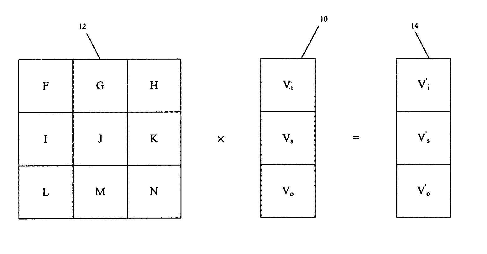
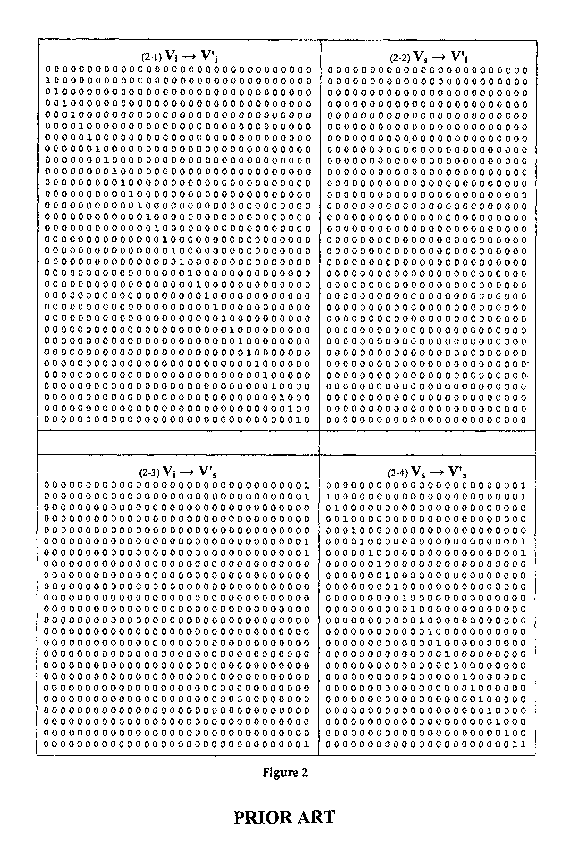
[0052]From this implementation the transfer matrix ACRC of FIG. 2 can be generated as described in the earlier list of bullet points. FIG. 2 is a transfer matrix, ACRC, for the CRC generator polynomial of FIG. 1, with a total of 56 rows and column...


PUM


Abstract

Apparatus for emulating the operation of an LFSR having at least one of one or more inputs and one or more outputs, wherein the state of the LFSR can be described by a state vector having sections describing the input or inputs, if any, of the LFSR, the contents of the LFSR and the output or outputs, if any, of the LFSR, wherein the state vector can be multiplied by a time shift matrix to time shift the state specified by the vector and wherein the apparatus comprises means for multiplying a first instance of the state vector by the matrix to produce a second instance of the state vector that is time shifted relative to the first instance and wherein one or both of the input and output sections of the state vector are dimensioned to accommodate, respectively, inputs that arrive at different times during the time shift specified by the matrix and outputs that are produced at different times during the time shift.

Description

BACKGROUND[0001]Scrambling-code generators and CRC generators and checkers are traditionally implemented in hardware as linear-feedback shift registers (LFSRs). However, such an implementation requires one clock cycle for every bit.[0002]It is sometimes desirable to process the data more quickly, which can be done by taking advantage of the fact that an LFSR can be represented mathematically as a transfer matrix A, defined so that NextState=A*CurrentState (modulo 2), where NextState and CurrentState are column vectors representing the state of the LFSR. In this way, an LFSR can be emulated.[0003]NB: The modulo 2 in the transfer function implies operations over GF(2) (i.e. everything is a bit and can only have the values 0 and 1), but this approach is certainly not limited to GF(2). However, this convention is used throughout this document since GF(2) is normally used in practical systems.[0004]For CRC, or any LFSR whose next state and / or output depend on a data input, NextState and ...

Claims


Application Information

Patent Timeline
Patent Type & Authority Patents(United States)
IPC IPC(8): G06F17/50H03M13/09H03M13/00G06F9/455G06F7/58G01R31/28
CPCG06F2207/583G06F17/5009G06F7/584H03M13/616G06F9/455H03M13/091G06F30/20
Inventor ALT, DANIEL, EDWARD
Owner MEDIATEK INC
Why Eureka
Try Eureka