
Pulse light source device and method for creating fs pulses

a light source device and pulse technology, applied in the direction of instruments, laser details, active medium materials, etc., can solve the problems of pump lasers having an inherent and fundamental limitation on average power, high repetition rate of e, and inability to achieve the effect of improving the amplitude stability of ps laser pulse output, reducing the cost of ps laser pulses, and simplifying timing stabilization of seeds

Active Publication Date: 2016-01-26
DEUTES ELEKTRONEN SYNCHROTRON DESY
View PDF9 Cites 12 Cited by
  • Summary
  • Abstract
  • Description
  • Claims
  • Application Information

AI Technical Summary

Benefits of technology

The invention is a new laser system that generates a specific type of laser pulse called a ps laser pulse. This laser system is unique because it can be designed to produce a high-quality ps laser pulse regardless of its set-up or geometry. It can operate for pulses as brief as sub-500 fs and as long as several ps. The system can also be designed to have a high repetition rate, ranging from 100 Hz to several million Hz. The ps laser pulse source uses a regenerative amplifier to provide a stable and scalable laser output. The system also includes a Yb-doped solid state pulse laser, which has advantages such as reduced heat load and improved scalability. The invention has applications in optical amplification and seeding stages in optical devices.

Problems solved by technology

These systems are very complex and subject to failure and instabilities.
Ti:Sapphire pump lasers have an inherent and fundamental limitation on average power due to the high heat load inside the crystals.
Even if Ti:Sapphire pump technology sustains high-pulse energy, it is limited in average power because of the high quantum defect causing thermal problems.
The current fiber technology provides high average power at the expense of pulse energy due to nonlinear effects inside the fiber gain medium.
Due to the above limitations, the conventionally used pump sources have general disadvantages in terms of non-scalability of the achievable spectrum and pump energy.
The driver of the WLG process is the second harmonic of the Yb-based driver laser, resulting in disadvantages in terms of stability and complexity of the set-up.
White-light generated at 515 nm is less stable and requires more complicated setup because of multi-photon absorption.
This movement introduces further instabilities, which are incompatible with CEP stabilization.
As a further disadvantage of [6], there is no multi-octave WLG from a CEP stable idler.

Method used


Image

  • Pulse light source device and method for creating fs pulses
  • Pulse light source device and method for creating fs pulses
  • Pulse light source device and method for creating fs pulses

Examples


Embodiment Construction

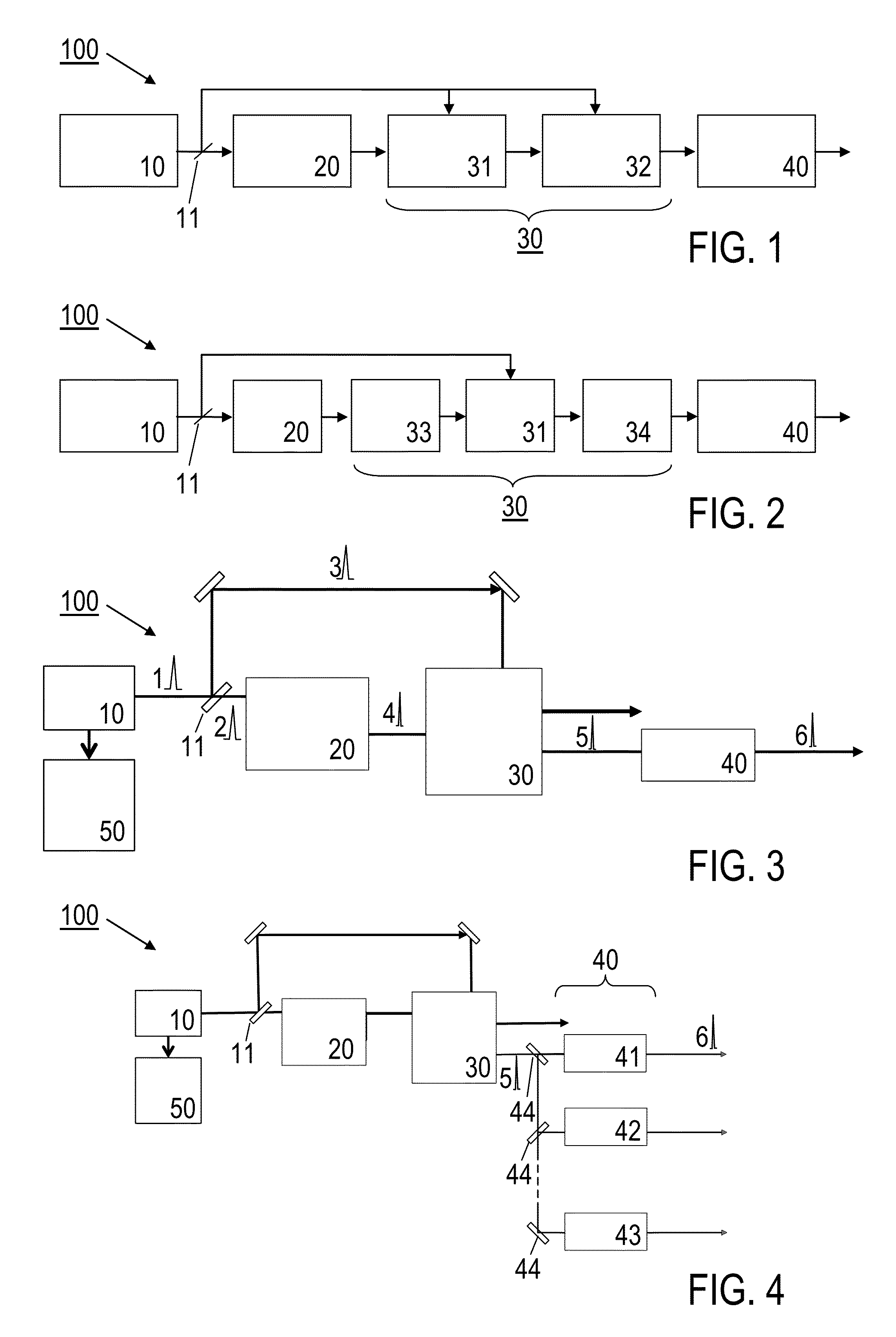
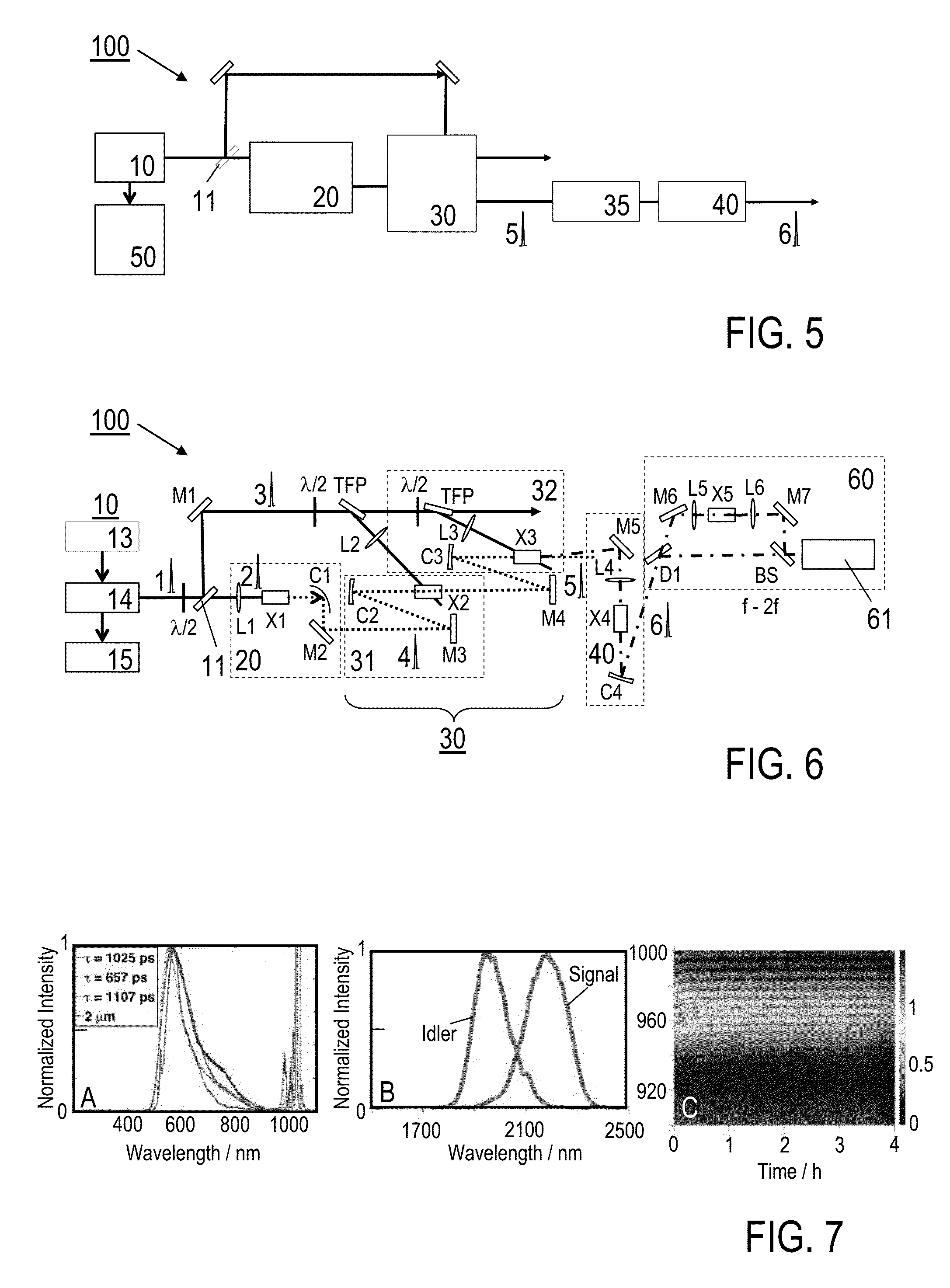
[0052]Features of preferred embodiments of the invention are described in the following with particular reference to the combination of spectral broadening and amplifier devices. Details of these devices are not described as far as they are known from conventional light pulse generation, manipulation and amplification techniques. In particular, the spectral broadening and amplifier devices are schematically illustrated. With a practical implementation of the invention, these devices may include further optical components, like e.g. mirrors, refractive optics, reflective optics, polarizers and / or sensors, e. g. as exemplified in FIG. 6.

[0053]The present invention provides a solution for the generation of CEP-stable, broadband pulses driven by slightly sub-ps pump pulses for seeding multi-octave spanning high-energy waveform synthesizers. The pulse light source device proposed by the invention can be used e.g. as a front-end for an Yb-based waveform synthesizer. The following descript...


PUM

PropertyMeasurementUnit
center wavelengthaaaaaaaaaa
pulse energyaaaaaaaaaa

Abstract

A pulse light source device for creating fs output pulses, includes a driver source device including a ps laser pulse source for creating a ps laser pulse output, a first beam splitting device for splitting the ps laser pulse output to first and second ps driver pulses, a first spectral broadening device for creating first fs driver pulses by spectrally broadening the first ps driver pulses, an optical parametric amplifier (OPA) device for creating CEP stabilized second fs driver pulses, and for seeding on the basis of the first fs driver pulses and pumping with the second ps driver pulses, wherein the second fs driver pulses include idler pulses of the OPA device, and a second spectral broadening device for creating the fs output pulses, and arranged to be driven on the basis of the second fs driver pulses. Furthermore, a method of creating fs output pulses is described.

Description

FIELD OF THE INVENTION[0001]The present invention relates to a pulse light source device, being adapted for creating fs (femtoseconds) output pulses, in particular to a broadband CEP-stable pulsed light source, and to a method for creating fs output pulses. Applications of the invention are available in the fields of seeding of pulse amplifiers, like OPAs or OPCPAs, generating of ultrashort, high energy pulses for scientific experiments, such as in attoseconds science, high harmonic generation, field-emission devices, seeding of optical waveform synthesizers, time-resolved spectroscopy, and micromachining.BACKGROUND OF THE INVENTION[0002]For describing the background of the invention, particular reference is made to the following publications:[0003][1] G. Cirmi et al. in “J. Opt. Soc. Am. B” vol. 25, no. 7, p. B62 (2008);[0004][2] G. M. Rossi et al. in CLEO 2014 conference, San Jose, USA, (Optical Society of America, Washington, D C, 2014), SF1E.3;[0005][3] S.-W. Huang et al in “Nat...

Claims


Application Information

Patent Timeline
Patent Type & Authority Patents(United States)
IPC IPC(8): H01S3/16H01S3/00G02F1/39H01S3/06
CPCG02F1/39H01S3/0606H01S3/1618H01S3/0604H01S3/0085G02F2001/392H01S3/005H01S3/0057H01S3/0092G02F1/392
Inventor CALENDRON, ANNE-LAURECANKAYA, HUSEYINROSSI, GIULIOCIRMI, GIOVANNIMUECKE, OLIVER D.FANG, SHAOBOKAERTNER, FRANZ X.
Owner DEUTES ELEKTRONEN SYNCHROTRON DESY
Learn More