
Process for xylenes production

a xylene and process technology, applied in the field of high temperature reforming process, can solve the problems of large amount of non-aromatic content remaining in the reformed naphtha, large amount of subsequent processing of non-aromatic content, and reduced selectivity, so as to improve reduce the acid cracking of c8 hydrocarbons, and increase the yield of xylen

Active Publication Date: 2015-12-01
UOP LLC
View PDF41 Cites 1 Cited by
  • Summary
  • Abstract
  • Description
  • Claims
  • Application Information

AI Technical Summary

Benefits of technology

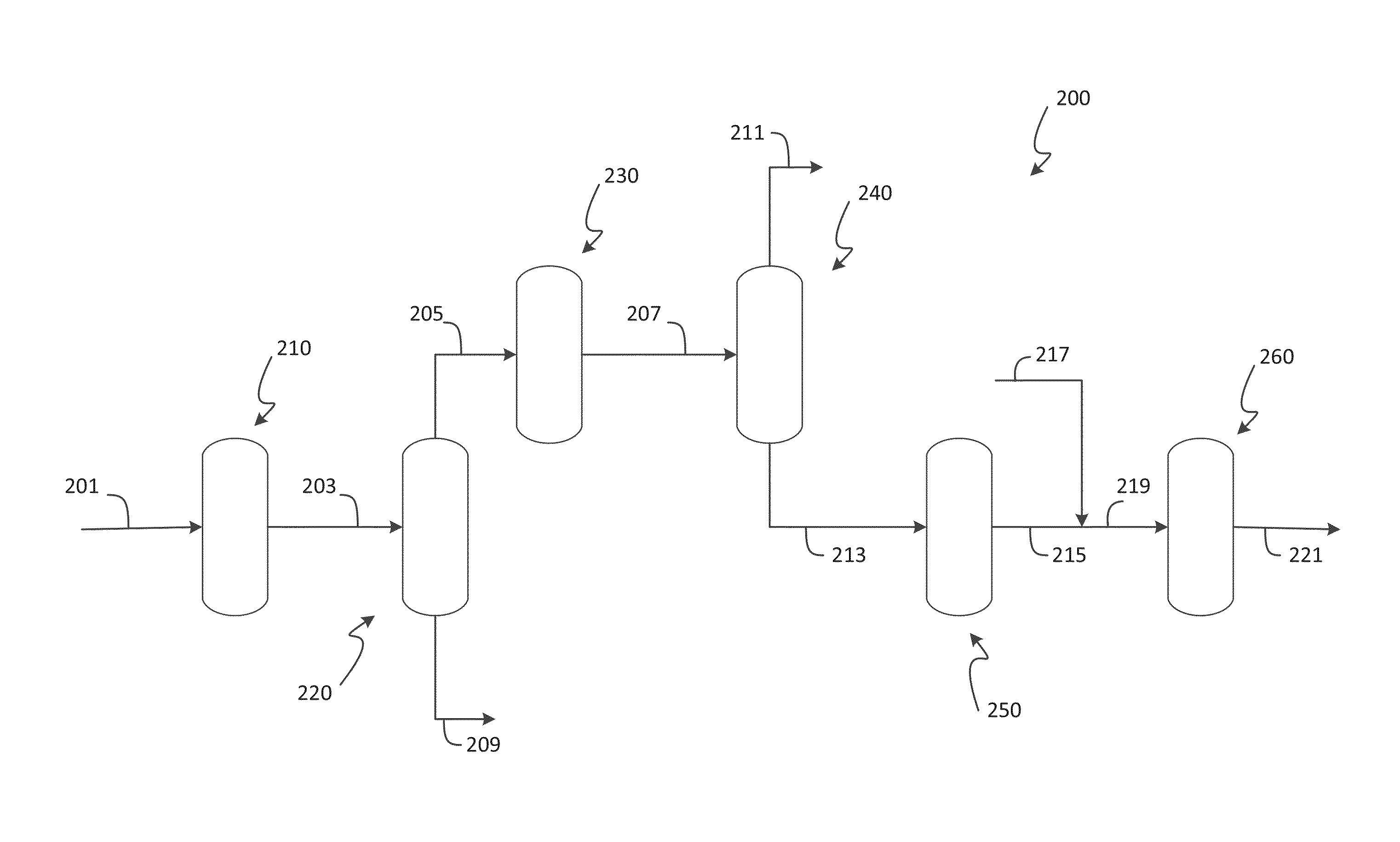
[0009]The inventors have made the surprising discovery that significantly more xylene may be produced in a reforming unit by co-feeding a naphtha stream and a C8 olefin stream, for example, from a C4 oligomerization unit. Further improvements in xylene yield may be obtained with reforming catalysts containing alkali metal, an alkaline earth metal or combinations thereof to reduce the acid cracking of the C8 hydrocarbons and to maximize conversion to xylenes. Finally, it has been discovered that operation of the reforming unit in a high temperature regime can improve activity of the aforementioned catalyst while still minimizing cracking reactions. Overall, selecting a co-feed containing C8 hydrocarbons, reforming catalyst comprising an alkali metal, an alkaline earth metal or combinations thereof, and a high temperature operating regime has resulted in significant improvements in a reforming process for the production of xylenes and other aromatics.

Problems solved by technology

Some of the reactions occurring during reforming, such as hydrocracking which produces light paraffin gases, are undesirable as they can have a deleterious effect on the yield of a desired product.
In addition, often present in xylene mixtures is ethylbenzene, which is occasionally recovered for styrene production, but usually is considered a less desirable component of C8 aromatics.
Moreover, the large amount of non-aromatic content remaining in the reformed naphtha requires substantial subsequent processing to remove the non-aromatics and to transalkylate the aromatics to benzene and xylene.
While the aforementioned dual-function catalysts are capable of catalyzing the dehydrocyclization of paraffins to aromatics such as para-xylene, there is always a trade-off where higher acidity catalysts have more activity but also have reduced selectivity due to increased hydrocracked products, particularly propanes and butanes.

Method used


Image

  • Process for xylenes production
  • Process for xylenes production
  • Process for xylenes production

Examples


example 1

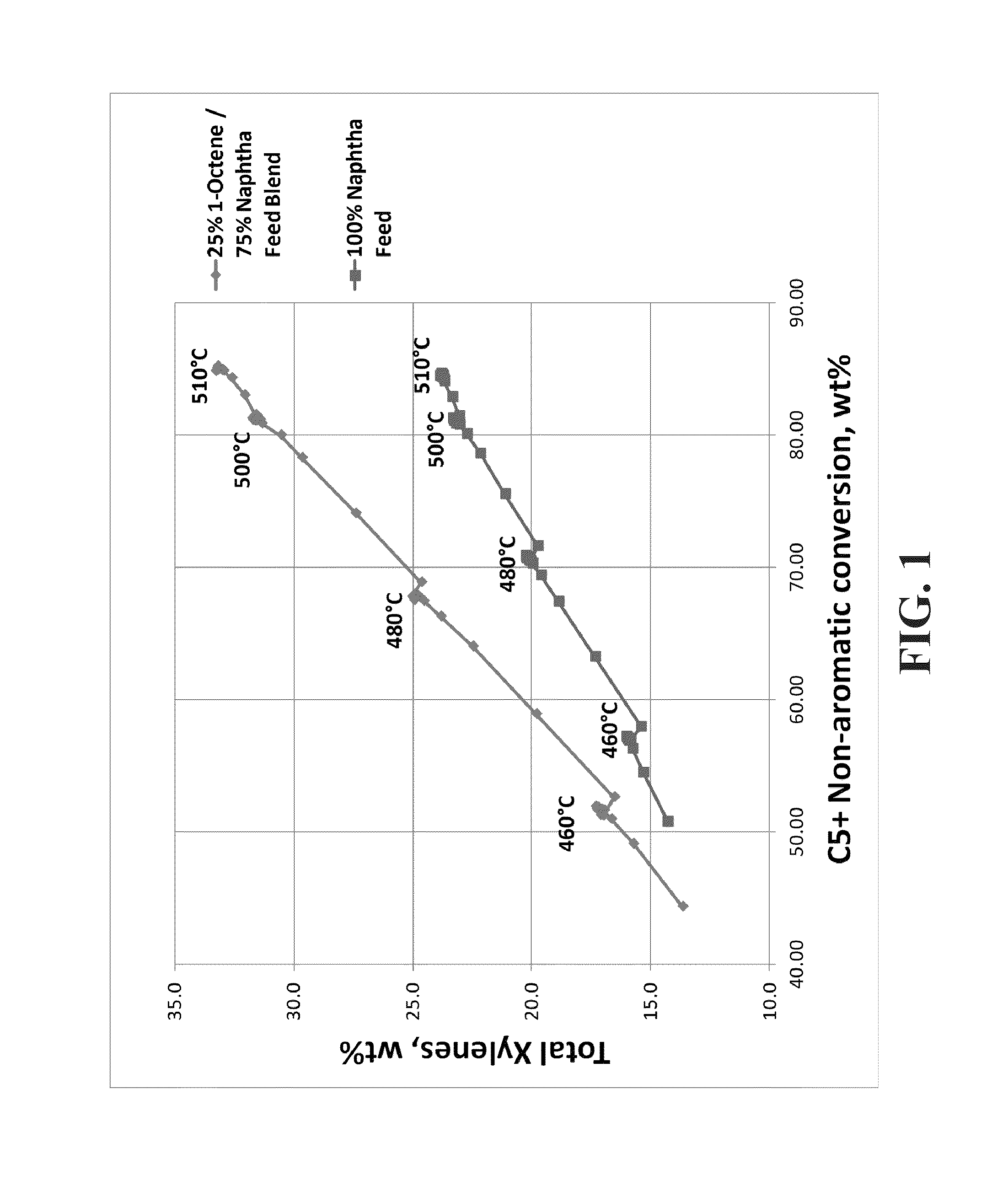
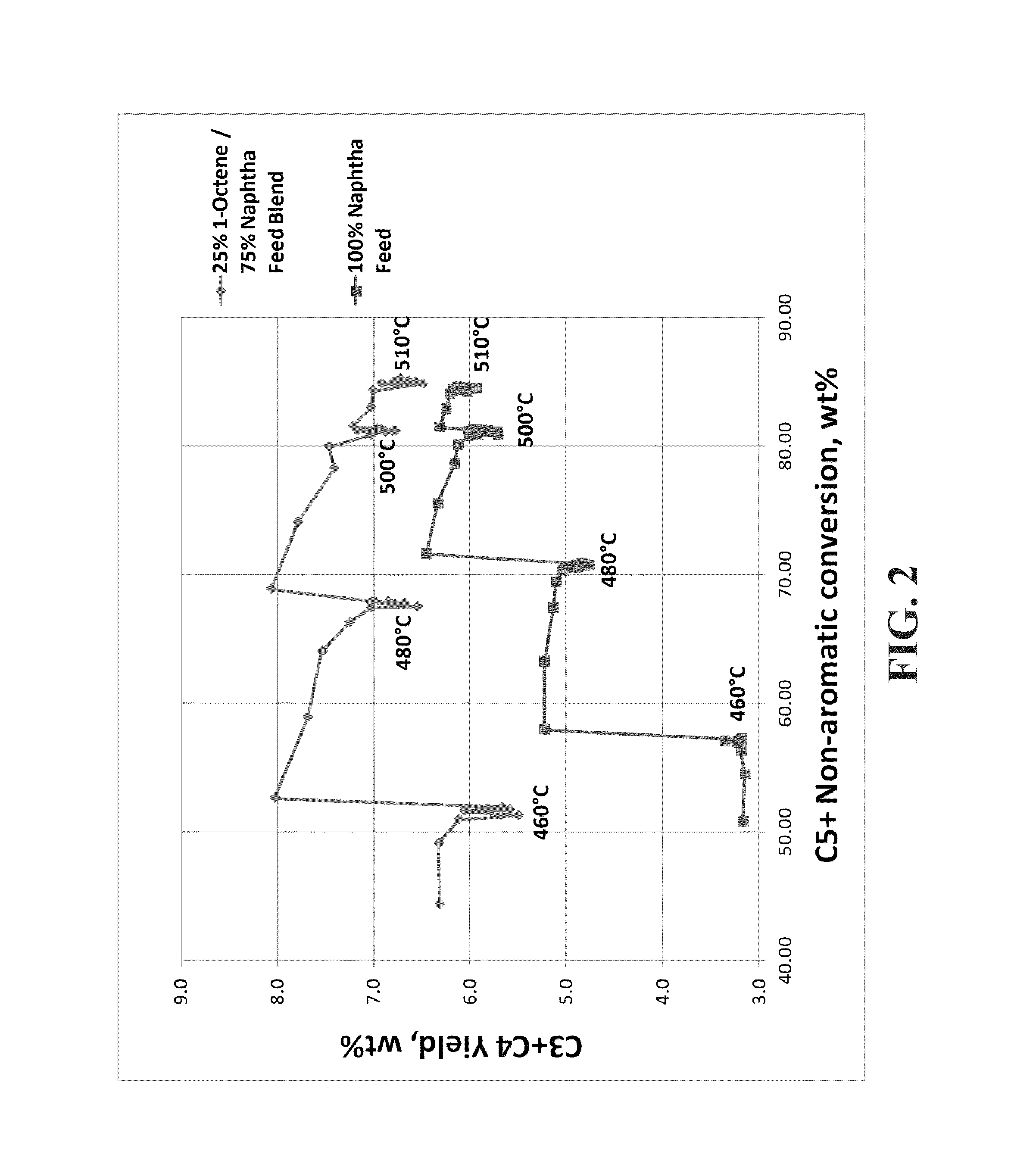
[0051]A feed blend was made using 25% 1-octene (100% linear C8) and 75% naphtha (61.2 wt % paraffins, 30.6 wt % naphthenes, 8.2 wt % aromatics, 329° F. end point by ASTM D86 distillation). The blend was fed to a reforming pilot plant operating at a liquid hourly space velocity (LHSV) of 1.0 hr−1, a molar ratio of hydrogen to hydrocarbon (H2:HC) of 6:1, 50 psi (gauge), with 12 hour temperature holds at 460° C., 480° C., 500° C., and 510° C. A 100% naphtha feed was also run separately over the same catalyst as a comparison case. The catalyst was a high-yield reference catalyst (RC1), which is a lanthanide containing spherical alumina catalyst with 0.30 wt % Sn, 0.29 wt % Pt, 1 wt % Cl and 0 wppm K. FIG. 1 shows that the C8+ naphtha blend produced significantly more xylenes than the naphtha alone. Furthermore, as the conversion increased as a function of increasing temperature, the amount of xylene produced increased for both feeds but there was a larger increase in xylenes for the C8+...

example 2

[0053]A performance evaluation was made using process simulation models to compare the material balance over the reforming unit when naphtha was the reformer feedstock and then when naphtha was mixed with a C8 olefinic stream, the second bottoms stream discussed above, comprising about 18 wt. % normal C8 olefin, 55 wt. % mono-branched C8 olefin, and 25 wt. % di-branched hydrocarbons, with only about 2 wt % tri-branched hydrocarbons. The operating conditions of the reforming unit included a liquid hourly space velocity (LHSV) of 2.30 hr−1, a molar ratio of hydrogen to hydrocarbon (H2:HC) of 2.8:1, and 50 psi (gauge). The catalyst in the simulation was a reforming catalyst containing Pt, Sn, and Cl on an alumina support. Table 1 shows that the mixed feed of C8 olefinic feed and naphtha blend produced significantly more xylenes than the naphtha alone, approximately 3 wt % more.

[0054]

TABLE 1Naphtha Only feedMixed FeedNaphtha feed to Reformer, lb / hr386,984386,984C8 Olefinic feed to Refor...

example 3

[0055]A series of spherical alumina catalysts was prepared, which contained 0.30 wt % Sn and a range of K between 0 and 2000 wppm. The catalysts also contained 0.29 wt % Pt and about 1 wt % Cl. 100% naphtha was used to pilot plant test the catalysts at 50 psi (gauge), a liquid hourly space velocity (LHSV) of 1.4 hr−1, a molar ratio of hydrogen to hydrocarbon (H2:HC) of 3:1, 8 barrels feed per ft3 catalyst (BPCF) and a research octane number of 104.3 as determined by gas chromatography. The data was adjusted with a kinetic model to a constant 80% conversion of C7 paraffins to show the yield selectivities at a constant conversion level. In addition to RC1, a second reference catalyst (RC2) was tested. RC2 is a lanthanide-free, spherical alumina catalyst with 0.30 wt % Sn, 0.29 wt % Pt, 1 wt % Cl and 0 wppm K.

[0056]FIG. 3 demonstrates that K-containing samples produced more xylenes than Catalysts A and B that do not contain K. Catalyst A was a high-yield reference catalyst, which is a ...


PUM

PropertyMeasurementUnit
temperatureaaaaaaaaaa

Abstract

Provided is a process for producing aromatics including the steps of preparing a C8 hydrocarbon stream, feeding a naphtha stream and the C8 hydrocarbon stream to a reforming unit, and reforming the naphtha stream and the C8 hydrocarbon stream to yield aromatics. The process combines a co-feed containing C8 hydrocarbons, an alkali / alkaline earth metal-containing reforming catalyst, and a high temperature operating regime to achieve significant improvements in a reforming process for the production of xylenes and other aromatics.

Description

FIELD OF THE INVENTION[0001]The present invention generally relates to a high temperature reforming process for the production of aromatic hydrocarbons wherein the reforming catalyst comprises an alkali metal, an alkaline earth metal or combinations thereof and the feed is a naphtha / C8 hydrocarbon co-feed.BACKGROUND OF THE INVENTION[0002]Catalysts having both a hydrogenation-dehydrogenation function and an isomerization / cracking function (“dual-function” catalysts) are used widely in many applications, particularly in the petroleum and petrochemical industry, to accelerate a wide spectrum of hydrocarbon-conversion reactions. The isomerization / cracking function generally relates to a material of the porous, adsorptive, refractory-oxide type containing an acid function. Typically, this material may be utilized as a support or carrier. The hydrogenation-dehydrogenation function is primarily contributed by a metal component (e.g., Group VIII metals) that is combined with the support.[00...

Claims


Application Information

Patent Timeline
Patent Type & Authority Patents(United States)
IPC IPC(8): C10G35/085C07C2/06C10G35/09C07C5/05C07C2/76
CPCC07C2/76C07C5/05C10G35/09C10G50/00C10G59/02C10G69/08C10G69/126C10G2400/30
Inventor LAPINSKI, MARK P.SERBAN, MANUELAKRUPA, STEVEN L.MOSER, MARK D.VANDEN BUSSCHE, KURT M.
Owner UOP LLC
Learn More