
Concept for combining coded data packets

a data packet and coding technology, applied in the field of payload data transmission concept, can solve the problems of inability to effectively utilize channel coding, interference or reception quality at the receiver, and often incoherent reception, so as to achieve effective utilization of incremental redundancy and/or code combining, increase code gain, and improve the effect of redundancy

Active Publication Date: 2015-11-10
FRAUNHOFER GESELLSCHAFT ZUR FOERDERUNG DER ANGEWANDTEN FORSCHUNG EV
View PDF12 Cites 3 Cited by
  • Summary
  • Abstract
  • Description
  • Claims
  • Application Information

AI Technical Summary

Benefits of technology

[0015]According to another embodiment, a receiver for receiving payload data transmitted from a transmitter to the receiver via a unidirectional communication to the receiver within a time interval by means of a plurality of channel-coded data packets, the receiver having no return channel that would lead to the transmitter for causing the transmitter to repeatedly transmit a channel-coded data packet in the event that decoding of the payload data has failed, each of the channel-coded data packets having packet core data corresponding to a packet identification of the respective channel-coded data packet, and the packet core data being coded with a channel code of higher redundancy than the payload data, may have: a means for receiving the plurality of channel-coded data packets within the time interval; and a decoder adapted to decode packet core data of a first received channel-coded data packet of the time interval, and, in the event of failure of error-free decoding of the first channel-coded data packet, to decode packet core data of at least one second received channel-coded data packet of the time interval so as to determine a suitable further channel-coded data packet of the time interval for combination with the first channel-coded data packet so as to obtain, on account of the combination, an increased code gain for decoding of the payload data.
[0034]Thus, embodiments of the present invention enable effective utilization of incremental redundancy and / or code combining even for unidirectional transmission modes without return channel, in particular in multipoint-to-point transmission systems wherein many subscribers transmit data to a central receiving point. As a result, a larger transmission range may be achieved than in conventional art by reducing a signal-to-noise ratio at the receiver. Alternatively, it is also possible to reduce the transmitting power necessitated while maintaining the transmission range. In addition, higher transmission reliability also results in the case of time-variant transmission channels as arise, for example, on account of mobile transmitters and / or receivers. I.e., the present invention enables incremental redundancy and / or code combining at the receiver without using a return channel from the receiver to a transmitter for this purpose.

Problems solved by technology

In this context, reception is often not coherent, and in most cases no channel coding is utilized.
However, with such communication systems, wherein a multitude of transmitters communicate with one receiver (multipoint-to-point), there is the problem that substantial interference may result at the receiver, depending on the number of transmitters and their random transmission times. Due to random transmission times of the transmitters and their number, which is often not predictable either, the interference or reception quality achieved at the receiver is not predictable.
Given a large number of transmitters M, many data packets from different transmitters will arrive at the central receiver at the same time, which leads to increased interference at the receiver and, thus, to aggravated receiving conditions.
Since the transmission times of the coded data packets are random or pseudorandom, the receiver will not be readily able to recognize which receive packets belong together.
It would take up too much computing time to try out all of the possible combinations of data packets, and it would not be possible, or necessitate a large amount of computing expenditure, to operate the system in real time.
Combining of received channel-coded data packets will only take place, therefore, if the redundancy information, or the error-corrected redundancy information, of a first received channel-coded data packet is not already sufficient for error-free decoding of the payload data.

Method used


Image

  • Concept for combining coded data packets
  • Concept for combining coded data packets
  • Concept for combining coded data packets

Examples


Embodiment Construction

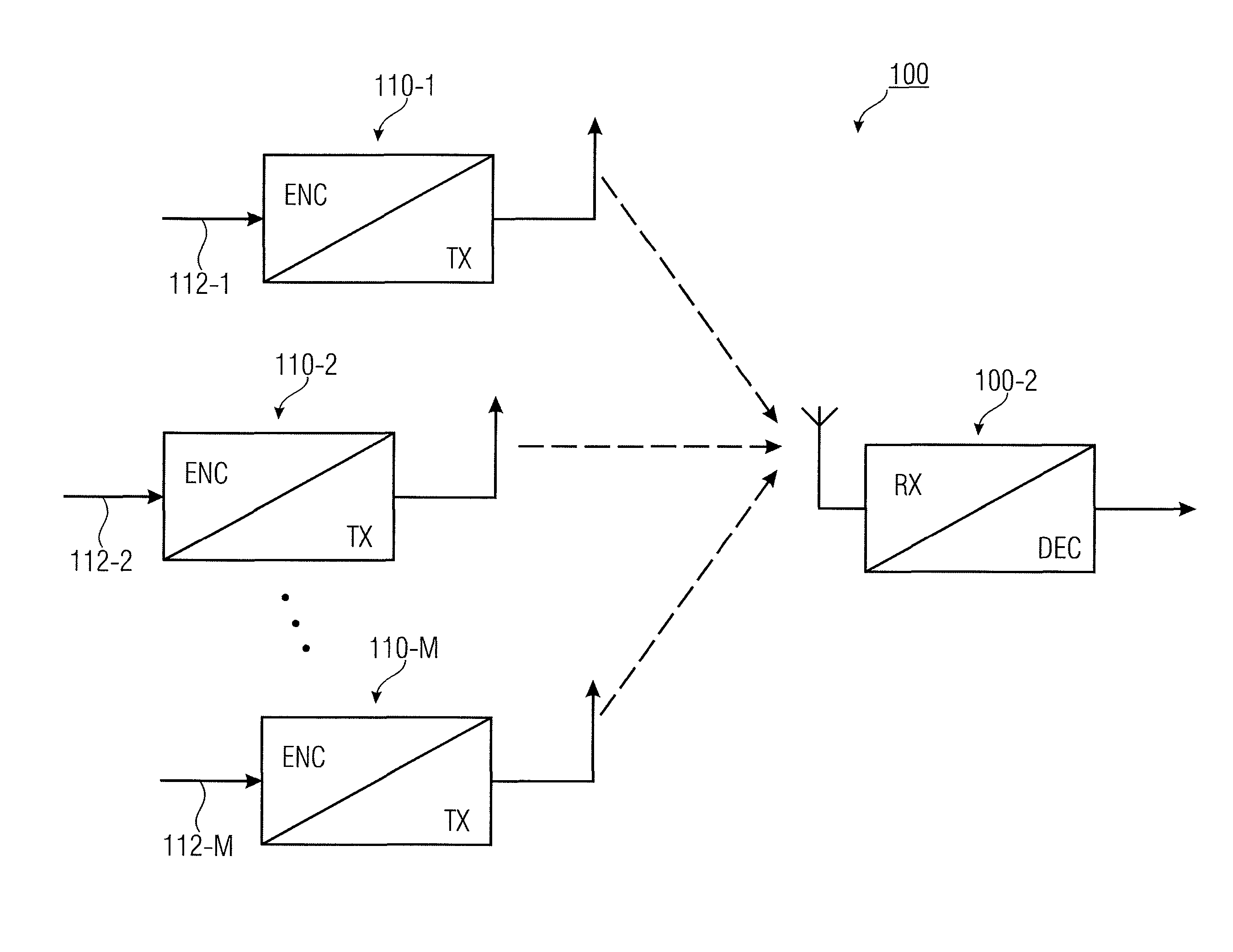
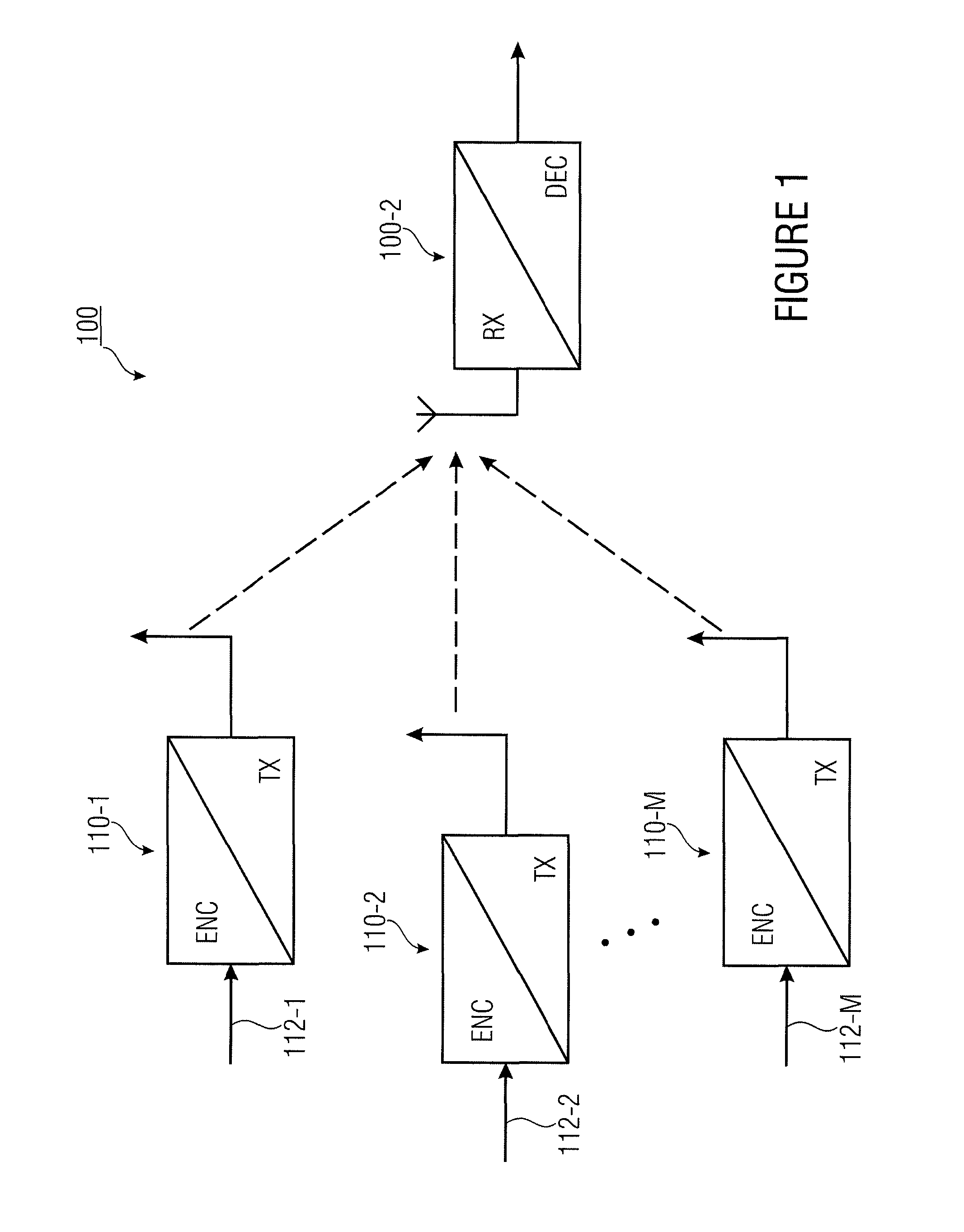
[0042]FIG. 1 schematically shows a multi-subscriber communication system 100 wherein a plurality of transmitters 110-m (m=1, 2, . . . , M) unidirectionally transmit their payload data 112-m to a central receiver 120 in each case, i.e. there is no return channel from the receiver 120 to any of the transmitters 110-m (m=1, 2, . . . , M).

[0043]Each of the transmitters 110-m (m=1, 2, . . . , M) comprises a means ENC for generating a plurality of channel-coded data packets from the payload data 112-m (m=1, 2, . . . , M). This may be interpreted to mean that the payload data 112-m (m=1, 2, . . . , M), which is to be transmitted within a transmission time interval in each case, has the plurality of channel-coded data packets associated with it. In addition, each transmitter 110-m (m=1, 2, . . . , M) comprises a means (transmitting unit) TX for transmitting the plurality of channel-coded data packets to the receiver 120 within the time interval.

[0044]One of the transmitters 110-m (m=1, 2, ....


PUM


Abstract

Concept for transmitting payload data from a transmitter to a receiver via a communication channel within a time interval, wherein channel-coded data packets are generated from the payload data, wherein each of the channel-coded data packets has packet core data corresponding to a packet identification of the respective channel-coded data packet, and wherein the packet core data is coded with a channel code of higher redundancy than the payload data. The channel-coded data packets are sent without any return channel to the receiver, which decodes packet core data of a first received channel-coded data packet of the time interval. If error-free decoding of the first channel-coded data packet fails, packet core data of at least one second received channel-coded data packet of the time interval are decoded to determine a suitable further channel-coded data packet for combination with the first channel-coded data packet to acquire, on account of the combination, an increased code gain for decoding of the payload data.

Description

CROSS-REFERENCE TO RELATED APPLICATIONS[0001]This application is a continuation of copending International Application No. PCT / EP2011 / 062118, filed Jul. 15, 2011, which is incorporated herein by reference in its entirety, and additionally claims priority from German Application No. 102010031411.0, filed Jul. 15, 2010, which is also incorporated herein by reference in its entirety.BACKGROUND OF THE INVENTION[0002]The present invention relates to a concept for transmitting payload data (useful data, Nutzdaten) in the form of a plurality of coded data packets that may be combined, at the receiving end, such that they are adapted to a transmission quality, so as to adapt a coding gain to the transmission quality and / or to a transmission situation. Embodiments of the present invention may be employed, in particular, in unidirectional multipoint-to-point transmission systems.[0003]For transmitting small payload data quantities as arise, e.g., with measuring devices, such as heating, elect...

Claims


Application Information

Patent Timeline
Patent Type & Authority Patents(United States)
IPC IPC(8): H03M7/00H04B7/26H04J3/24H03M13/00H04L1/00H04L1/18H03M13/23H03M13/09
CPCH04B7/2643H03M13/6306H03M13/6362H04L1/0083H04L1/007H04L1/0072H03M13/09H03M13/23H04L1/1819H04L2001/0092
Inventor KILIAN, GERDTASCH, ANDREASBERNHARD, JOSEFKOCH, WOLFGANGNICKEL, PATRICKGERSTACKER, WOLFGANG
Owner FRAUNHOFER GESELLSCHAFT ZUR FOERDERUNG DER ANGEWANDTEN FORSCHUNG EV
Learn More