Light emitting device with selection circuit for image signal polarity inversion
a light-emitting device and image signal technology, applied in static indicating devices, solid-state devices, instruments, etc., can solve the problems of large load on the signal line driver circuit, low market penetration rate of light-emitting devices, and high production cost of light-emitting devices
- Summary
- Abstract
- Description
- Claims
- Application Information
AI Technical Summary
Benefits of technology
Problems solved by technology
Method used
Image
Examples
embodiment 1
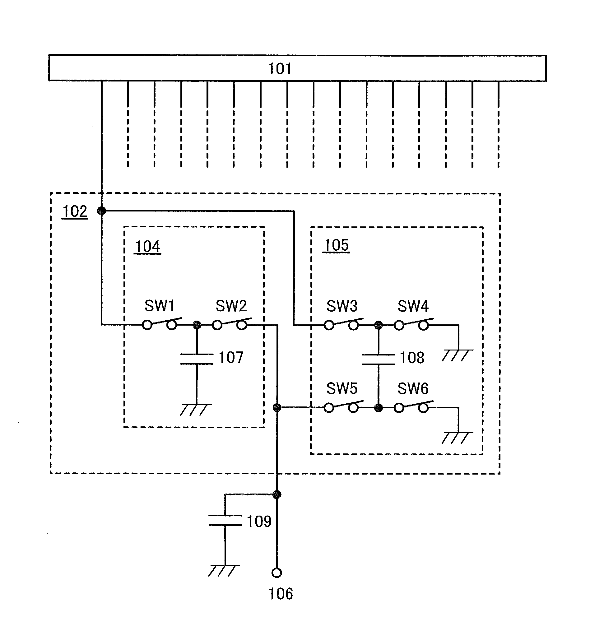
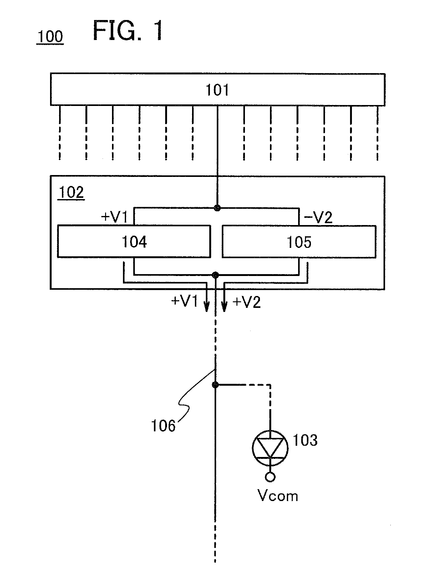
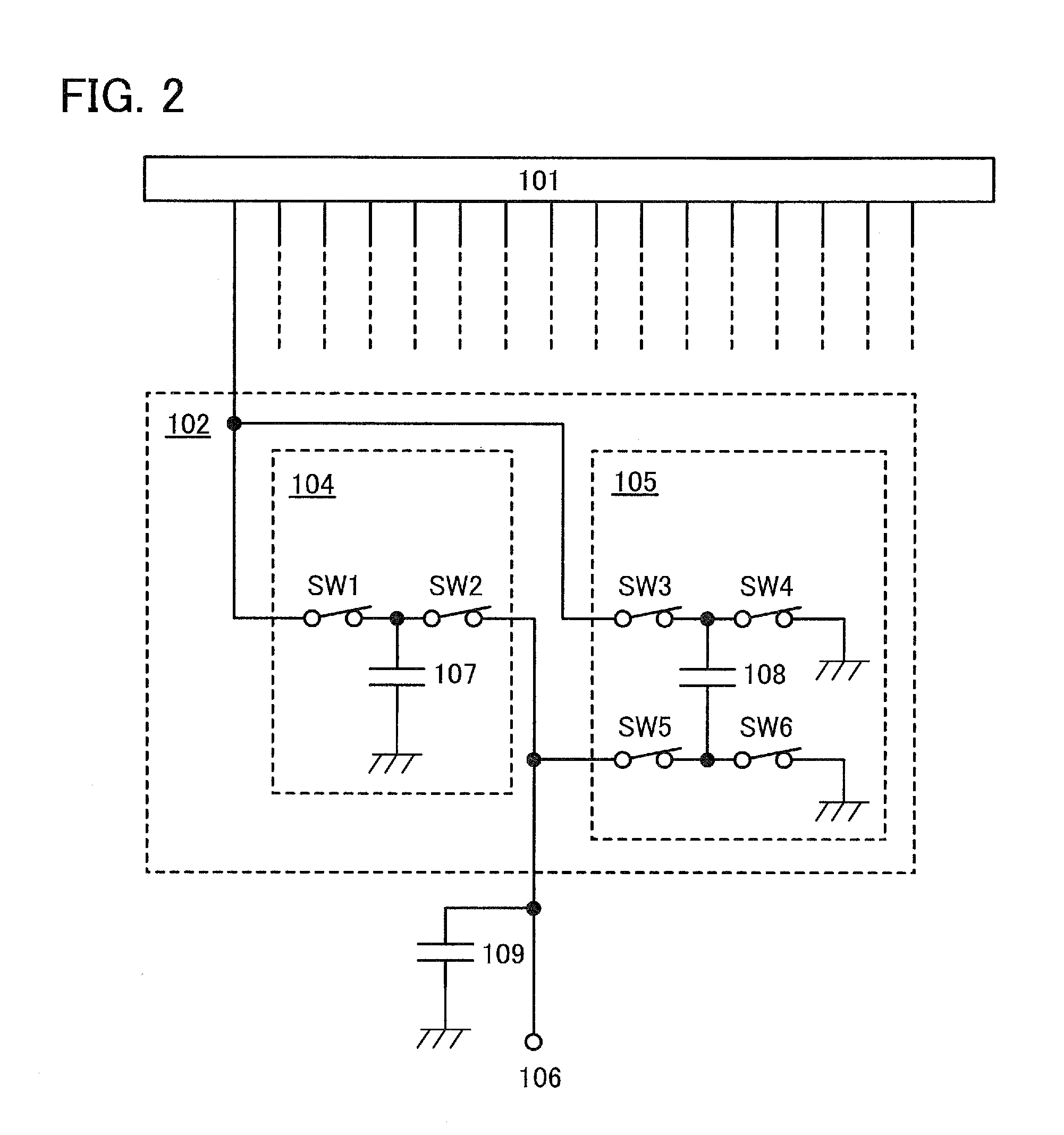
[0034]FIG. 1 illustrates a structure example of a light-emitting device 100 according to one embodiment of the present invention. The light-emitting device 100 in FIG. 1 includes a signal line driver circuit 101 generating a first image signal having a positive polarity and a second image signal having a negative polarity, a selection circuit 102 holding the first image signal having a positive polarity and the second image signal having a negative polarity and making the two image signals have the same polarity by converting the polarity of one of the two held image signals into an opposite polarity, and a light-emitting element 103 whose luminance is sequentially determined in response to the two image signals.
[0035]Specifically, the signal line driver circuit 101 has a function of converting an input serial image signal into a parallel image signal and outputting the parallel image signal. Further, among image signals output from the signal line driver circuit 101, one of a first...
embodiment 2
[0076]FIG. 7 is a block diagram illustrating a structure example of a light-emitting device according to one embodiment of the present invention. A light-emitting device 200 in FIG. 7 includes a pixel portion 201 in which a light-emitting element is provided in each pixel, and driver circuits controlling the operation of the pixel portion 201. The light-emitting device 200 in FIG. 7 includes a scan line driver circuit 202, a signal line driver circuit 203, and a selection circuit 204 as the driver circuits.
[0077]The scan line driver circuit 202 has a function of selecting pixels included in the pixel portion 201. The signal line driver circuit 203 has a function of outputting an image signal having a positive polarity and an image signal having a negative polarity that correspond to pixels selected by the scan line driver circuit 202. The selection circuit 204 has a function of inverting the polarity of one of the image signal having a positive polarity and the image signal having a...
embodiment 3
[0096]In this embodiment, a specific structure example of a pixel of a light-emitting device according to one embodiment of the present invention is described. Note that a transistor in the pixel corresponds to a semiconductor element in one embodiment of the present invention.
[0097]FIG. 8A shows an example of a circuit diagram of a pixel 300. The pixel 300 includes a transistor 301 controlling input of an image signal to the pixel 300, a light-emitting element 302, a transistor 303 controlling the value of current supplied to the light-emitting element 302 in response to an image signal, and a capacitor 304 for holding the potential of an image signal.
[0098]The potential of one of an anode and a cathode of the light-emitting element 302 is controlled in response to an image signal input to the pixel 300. The reference potential Vcom is applied to the other of the anode and the cathode of the light-emitting element 302. The luminance of the light-emitting element 302 is determined b...
PUM
 Abstract
Description
Claims
Application Information
 - R&D
- Intellectual Property
- Life Sciences
- Materials
- Tech Scout
- Unparalleled Data Quality
- Higher Quality Content
- 60% Fewer Hallucinations
Browse by: Latest US Patents, China's latest patents, Technical Efficacy Thesaurus, Application Domain, Technology Topic, Popular Technical Reports.
© 2025 PatSnap. All rights reserved.Legal|Privacy policy|Modern Slavery Act Transparency Statement|Sitemap|About US| Contact US: help@patsnap.com


