Liquid level detection device

a detection device and liquid level technology, applied in the direction of measurement devices, level indicators, instruments, etc., can solve the problems of bi-stable snaps, specialized and costly bi-stable snaps, and floats that are subject to fouling, etc., and achieve low impedance and high impedance input.

Active Publication Date: 2015-11-10
DIVERSITECH
View PDF8 Cites 6 Cited by
  • Summary
  • Abstract
  • Description
  • Claims
  • Application Information

AI Technical Summary

Benefits of technology

[0009]In order to sense the level of liquid in the tank and thereby control the operation of the motor of the centrifugal pump, an alarm, or shut off the HVAC system if necessary, a liquid level detection device is employed that can reject false signals common to electronic liquid level detection systems, which false signals are caused by contamination of the sensing electrode and the containment tank and by external electrical noise sources. The level detection device of the present invention includes an electronic signal source for generating one or more signals (multi-phase or multi-frequency), a lock-in amplifier, and a reference signal directly connecting the signal source to the lock-in amplifier. The signals generated by the signal source are connected to one or more low impedance signal electrodes. The low impedance signal electrodes may be positioned at different levels inside the tank so that at any given level of liquid in the tank, each individual low impedance signal electrode may or may not be in contact with the liquid in the tank. Alternatively, the low impedance signal electrodes may be attached to the external wall of the tank at different levels. Because each signal electrode is connected to a low impedance signal source output, the signal electrode is low impedance and immune to the perils of the high impedance input typical of capacitance sensors. Particularly, because each level detecting signal is emitted from a low impedance output, a bridge of slime or debris between adjacent signal electrodes cannot conduct a false signal onto another level electrode (output) as can be the case with high impedance capacitive or conductance sensors where the level detection electrode is at any time used as an input. This use of low impedance outputs for the signals is significant even without the added noise rejection and gain provided by a lock-in-amplifier.

Problems solved by technology

The condensate pump float is in contact with the water in the tank and is subject to fouling from debris and algae buildup.
A molded float has seams, which may fail causing the float to sink or malfunction.
The float switch that is used to control the on / off operation of the electric motor is often a specialized and costly bi-stable snap-action switch.
Capacitance plates that are in contact with the water in the tank are subject to fouling based on the buildup of debris or algae.
The fouling of the capacitance plate adversely affects the performance of the capacitive sensor.
These high impedance circuits work well to detect water and other fluids, but due to their sensitive nature are subject to minute leakage currents created by dirty insulators, slime and mineral buildup in the vicinity of the sensing electrodes.
A high impedance sensor may also fail from buildup which functions to connect it to an adjacent sensor.
Additional failure modes can occur from stray radio frequency fields, electrostatic buildup and other outside electromotive forces which can easily influence the high impedance capacitive sensor input.
Because of the high impedance, the capacitance plates pick up extraneous background interference that can further affect the accuracy of the capacitive sensors.
Such sonic detectors are difficult to calibrate and may be affected by extraneous sound waves such as those created by the pump motor.

Method used


Image

  • Liquid level detection device
  • Liquid level detection device
  • Liquid level detection device

Examples


first embodiment

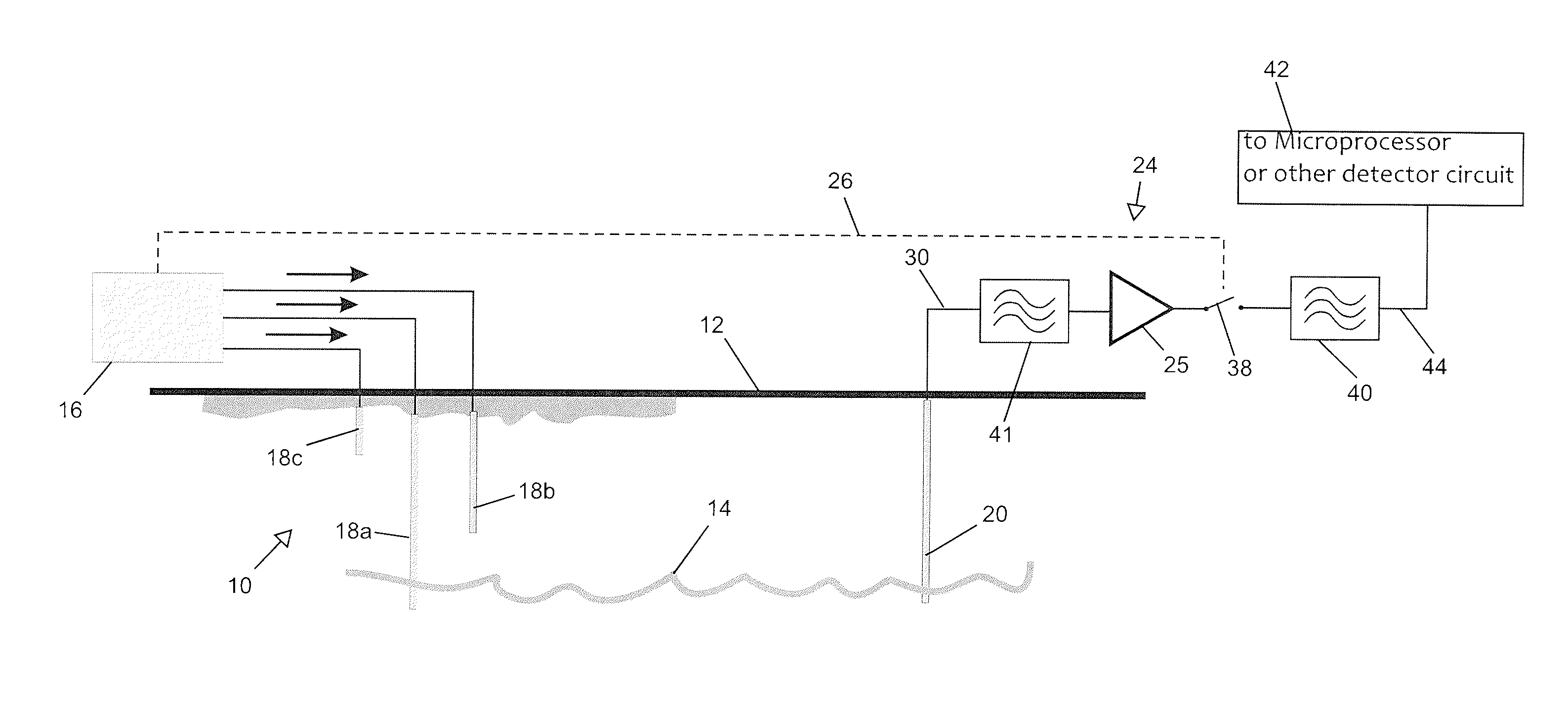
[0024]FIG. 2 discloses a liquid level detection device 10 for detecting the level of liquid 14 in a tank 12 in accordance with the present invention. The liquid level detection device 10 comprises a signal source 16, a first low impedance signal electrode 18a (low water level), a second low impedance signal electrode 18b (intermediate water level), a third low impedance signal electrode 18c (critical high water level), an antenna 20, a sensing circuit comprising a lock-in amplifier 24, and a detector 42.

[0025]In accordance with the present invention, the term “low impedance” means that, by way of example, the signal electrodes are connected to a microcontroller output, a logic gate output, or other low-impedance solid-state output with an impedance in the range of 0 to 500 ohms and therefore significantly less apt to be perturbed than prior art level sensing electrodes that are capacitance sensors or signal inputs with typical input impedances in the range of 10,000 to Ser. No. 10 / 0...

second embodiment

[0031]FIG. 3 shows a liquid level detection device 110 for determining the level of liquid 14 in the tank 12. The liquid level detection device 110 differs from the liquid level detection device 10 based on the arrangement of a first low impedance signal electrode 118a and a second low impedance signal electrode 118b and on the location of an antenna 120. The low impedance signal electrodes 118a and 118b are plates, and as shown in FIG. 3, the low impedance signal electrodes 118a and 118b are attached to the outside of a wall 119 of the tank 12. The antenna 120 is attached to the outside of an opposite wall 121 of the tank 12. The first low impedance signal electrode 118a extends across the width of the wall 119 and extends vertically from near the bottom of the tank 12 to a mid-point gap 123. The second low impedance signal electrode 118b extends across the width of the wall 119 and extends vertically from near the top of the tank 12 to the mid-point gap 123. The low impedance sign...


PUM


Abstract

A liquid level detection device includes a signal source for generating one or more unique signals on low impedance signal electrodes, a lock-in amplifier, and a reference signal directly connecting the signal source to the lock-in amplifier. The unique signals generated by the signal source are connected to one or more low impedance signal electrodes. The low impedance signal electrodes may be positioned at different levels inside the tank so that at any given level of liquid in the tank, each low impedance individual electrode may or may not be in contact with the liquid in the tank. Alternatively, the low impedance signal electrodes may be attached to the external wall of the tank at different levels. An antenna is connected to an input of the lock-in amplifier. The antenna may be placed inside the tank at the lowest level for the liquid, or the antenna may be attached to the outside wall of the tank near the bottom of the tank.

Description

CROSS REFERENCE TO RELATED PATENT APPLICATIONS[0001]This invention claims priority from U.S. Provisional Patent Application No. 61 / 583,339, filed Jan. 5, 2012, which is hereby incorporated by reference.FIELD OF THE INVENTION[0002]This invention relates to a liquid level detection device and more particularly relates to a liquid level detection device that includes low impedance signal electrodes and a lock-in amplifier for determining the level of liquid in a tank or other liquid storage vessel.BACKGROUND OF THE INVENTION[0003]Liquid handling systems generally require a means for determining the level of a liquid in a tank or other liquid storage vessel. One such liquid handling system is a condensate pump for use with a heating, ventilation, and air-conditioning (HVAC) system. A conventional condensate pump has a tank or reservoir for collecting condensate from the evaporator of the HVAC system. A centrifugal pump transfers the condensate from the tank to a remote location for disp...

Claims


Application Information

Patent Timeline
Patent Type & Authority Patents(United States)
IPC IPC(8): G01F23/26G01F25/00
CPCG01F23/26G01F23/266G01F23/265G01F25/0061G01F23/244G01F25/20
Inventor WARD, CHARLES BARRY
Owner DIVERSITECH
Why Eureka
Try Eureka