
Method and system for optically evaluating proximity to the inferior alveolar nerve in situ

a technology of proximity and in situ evaluation, applied in the field of methods and systems for evaluating proximity to a target, can solve the problems of loss of sensation in the anterior mandible area, risk of intraosseous canal breach, and inconvenient operation of implant procedures, and achieve the effect of low coheren

Active Publication Date: 2015-11-10
DR HASSAN GHADERI MOGHADDAM +1
View PDF145 Cites 5 Cited by
  • Summary
  • Abstract
  • Description
  • Claims
  • Application Information

AI Technical Summary

Benefits of technology

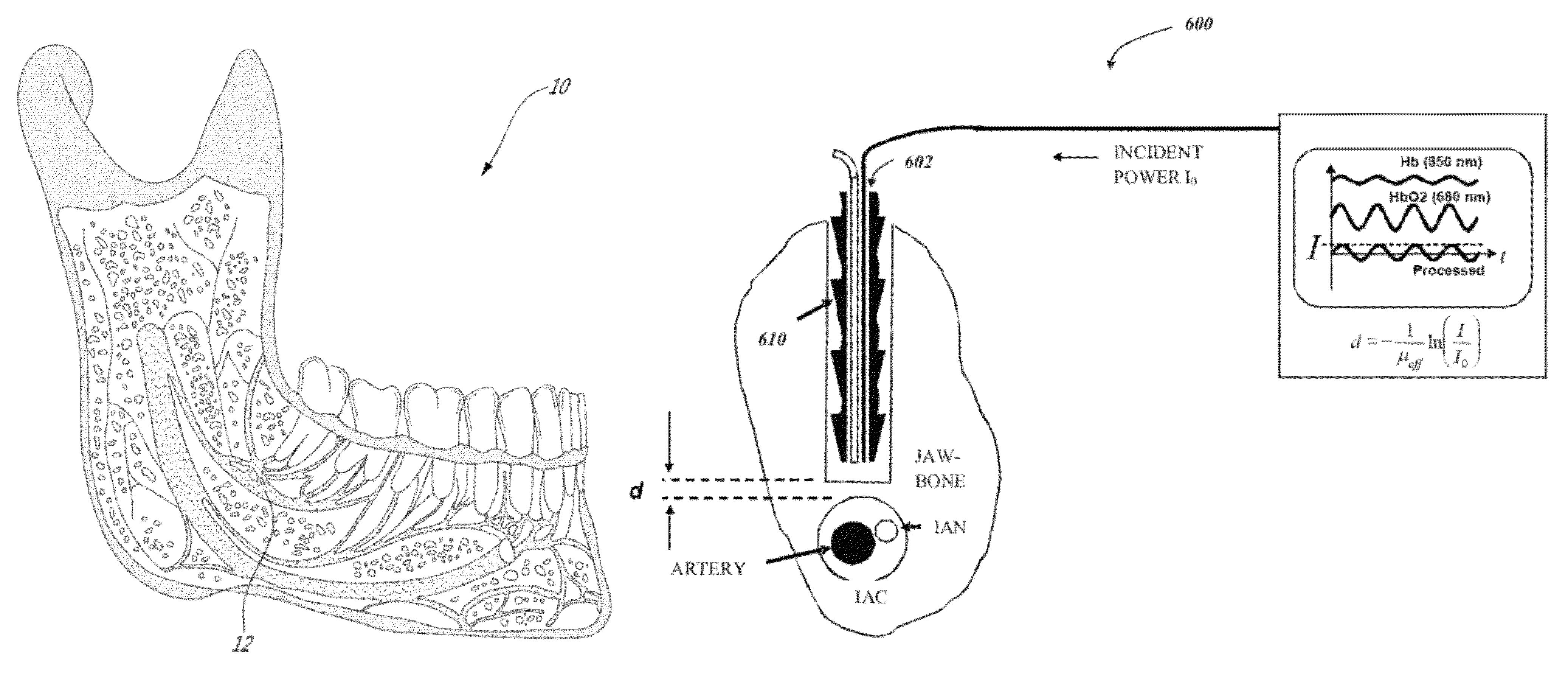
The present invention provides a spectral absorption probe system for evaluating the proximity of an artery using a light source and a collection optical fiber. The system includes an excitation optical fiber and a collection optical fiber, which are both embedded in a single optical fiber. The system can be fibered and integrated within a hollow core of a drill bit. The system uses low coherence interferometry to evaluate the distance of the artery based on the back-scattered light received by the collection optical fiber. The system can be operated in A-mode or B-mode and provides conical imaging. The technical effects of the invention include improved accuracy in evaluating the proximity of an artery and improved imaging quality.

Problems solved by technology

Implant procedures are not without complications.
However, the drilling of a large implant channel within the mandible carries a risk of breaching an intraosseous canal which encloses the inferior alveolar nerve (IAN).
Disruption of the IAN can lead to loss of sensation in the anterior mandible area, such as paresthesia or numbness to the lower lip, due to the disruption of the mental nerve, which is the terminal branch of the IAN and is the neural bundle serving this area.
The loss of sensation for the patient is certainly undesirable.
This measurement error can result in nerve damage.

Method used


Image

  • Method and system for optically evaluating proximity to the inferior alveolar nerve in situ
  • Method and system for optically evaluating proximity to the inferior alveolar nerve in situ
  • Method and system for optically evaluating proximity to the inferior alveolar nerve in situ

Examples


Embodiment Construction

[0072]Anatomy Background

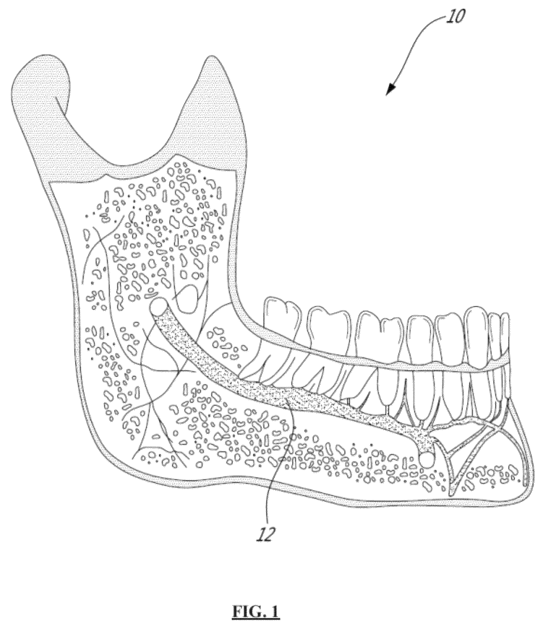
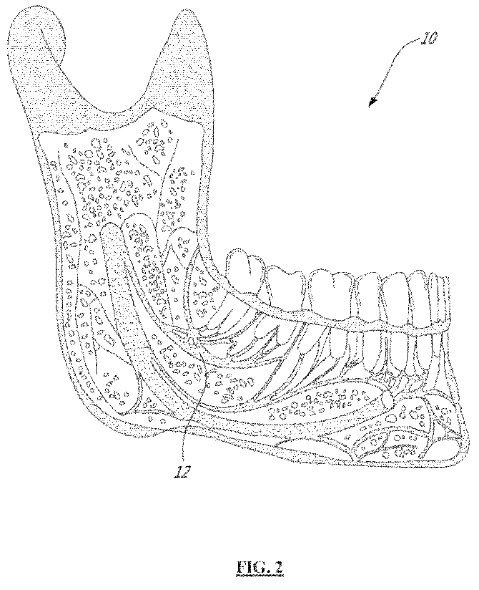
[0073]Referring to FIGS. 1 and 2 which show Sagittal sections of a mandible 10, the inferior alveolar nerve 12 (IAN) is a branch of the mandibular nerve, which stems from the trigeminal nerve system. The IAN 12 enters an intraosseous canal through the mandibular foramen in the posterior portion of the mandible. The nerve continues its path within the mandible 10 and then exits through the mental foramen. Throughout the length of the osseous canal, the IAN 12 is closely associated with the inferior alveolar artery and both structures are covered in a tough sheath of connective tissue. The diameter of the entire bundle varies between patients but averages at 2.53±0.29 mm [C. D. Morris et al., J. Oral Maxillo. Surg., 68:2833-2836, 2010].

[0074]The intraosseous canal is a hollow channel and in most cases has borders with defined walls which may be consistent throughout the length of the canal. The diameter of this canal is known to be 2.0 to 2.6 mm. The canal wall...


PUM


Abstract

A low coherence interferometry probe system for evaluating proximity to a tissue layer, comprising a low coherence light source, an excitation optical fiber to bring the low coherence excitation light near the tissue layer and a collection optical fiber for capturing back-scattered light from the tissue layer. The probe system comprises an interferometry sub-system and a processor for evaluating a distance to the tissue layer. There is also provided a spectral absorption probe system for evaluating proximity to an artery, comprising a light source excitation light having a wavelength adapted for absorption by blood chromophores, an excitation optical fiber and a collection optical fiber. The probe system comprises a light detector and a processor for determining a distance to the artery using the Beer-Lambert law of light absorption with a value for surrounding tissue attenuation coefficient (μeff). A probe system combining low coherence interferometry and spectral absorption is also provided.

Description

CROSS REFERENCE TO RELATED APPLICATION[0001]This application claims priority of U.S. Provisional Patent Application Ser. No. 61 / 477,787 filed on Apr. 21, 2011 and entitled “METHOD AND SYSTEM FOR OPTICALLY EVALUATING PROXIMITY TO THE INFERIOR ALVEOLAR NERVE IN SITU”, the specification of which is hereby incorporated by reference.TECHNICAL FIELD[0002]The invention relates to methods and systems for evaluating proximity to a target, more specifically, for evaluating proximity to a nerve.BACKGROUND OF THE ART[0003]Dental implants are a widely accepted treatment for the partially or completely edentulous patient. Dental implants are the fastest growing procedure in dentistry today. It is a 1 billion dollar industry in the USA. Dental implants offer a suitable alternative to mucosal adhering dentures and allow a more natural option for the patient. Implants have a high success rate when given proper care and when post-surgical instructions are followed. Dental implants can be in the form ...

Claims


Application Information

Patent Timeline
Patent Type & Authority Patents(United States)
IPC IPC(8): A61B6/00A61C19/04A61B5/00A61B5/1455A61B6/51
CPCA61B5/0075A61B5/4542A61B5/489A61B5/4893A61C19/04A61B5/14551A61B5/0066A61B2090/306A61B2034/2057A61B5/0261A61B17/1673A61B17/1703A61C1/084A61C1/088A61C8/0089
Inventor MOGHADDAM, HASSAN GHADERIGALLANT, PASCALMERMUT, OZZYVEILLEUX, ISRAEL
Owner DR HASSAN GHADERI MOGHADDAM
Learn More