
Automated analysis of compilation processes in a graphical specification and constraint language

a compilation process and automatic analysis technology, applied in the field of programming, can solve the problems of application constraints, application implementation in programmable hardware, application footprint constraints, etc., and achieve the effect of improving future compilations of desktop algorithms

Active Publication Date: 2015-09-15
NATIONAL INSTRUMENTS
View PDF20 Cites 5 Cited by
  • Summary
  • Abstract
  • Description
  • Claims
  • Application Information

AI Technical Summary

Benefits of technology

The patent text describes a system and method for compiling and implementing applications and programs using a novel method. The system can automatically analyze and modify the design of the program at different stages of the code compilation process to account for any previous issues. This helps improve the overall quality of the program design. The system can be used with different types of hardware and can automatically optimize the design for future compilations. Overall, the technology enhances the efficiency and quality of coding across various platforms.

Problems solved by technology

Moreover, such applications may be subject to various constraints, e.g., with respect to timing, resource usage, throughput, etc.
For example, applications to be implemented in programmable hardware, such as a field programmable gate array (FPGA) may be subject to constraints regarding the application's footprint, i.e., area used, on the FPGA.
The aforementioned applications implemented in programmable hardware may further be subject to timing and resource constraints with corresponding implications that are often difficult and / or impossible to predict when making choices while constructing high-level models and / or code representative of the applications.
In general, the problem occurs anytime an internal or external tool is invoked to finish high-level compilation that started from the first tool.
Prior art techniques for specifying and implementing such applications therefore require significant manual analysis and testing, which is difficult, tedious, and error prone.

Method used


Image

  • Automated analysis of compilation processes in a graphical specification and constraint language
  • Automated analysis of compilation processes in a graphical specification and constraint language
  • Automated analysis of compilation processes in a graphical specification and constraint language

Examples


Embodiment Construction

Terms

[0026]The following is a glossary of terms used in the present application:

[0027]High-Level Synthesis—sometimes referred to as C synthesis, electronic system level (ESL) synthesis, algorithmic synthesis, or behavioral synthesis, is intended to refer to an automated design process that interprets an algorithmic description of a desired behavior and creates hardware that implements that behavior. The starting point of a high-level synthesis flow may be ANSI C / C++ / SystemC code or the like. The code may be analyzed, architecturally constrained, and scheduled to create a register transfer level hardware design language (HDL), which may then be synthesized to the gate level by the use of a logic synthesis tool. Hardware design may be created at a variety of levels of abstraction. The commonly used levels of abstraction include gate level, register transfer level (RTL), and algorithmic level. High-level synthesis tools may handle the microarchitecture and transform untimed or partiall...


PUM


Abstract

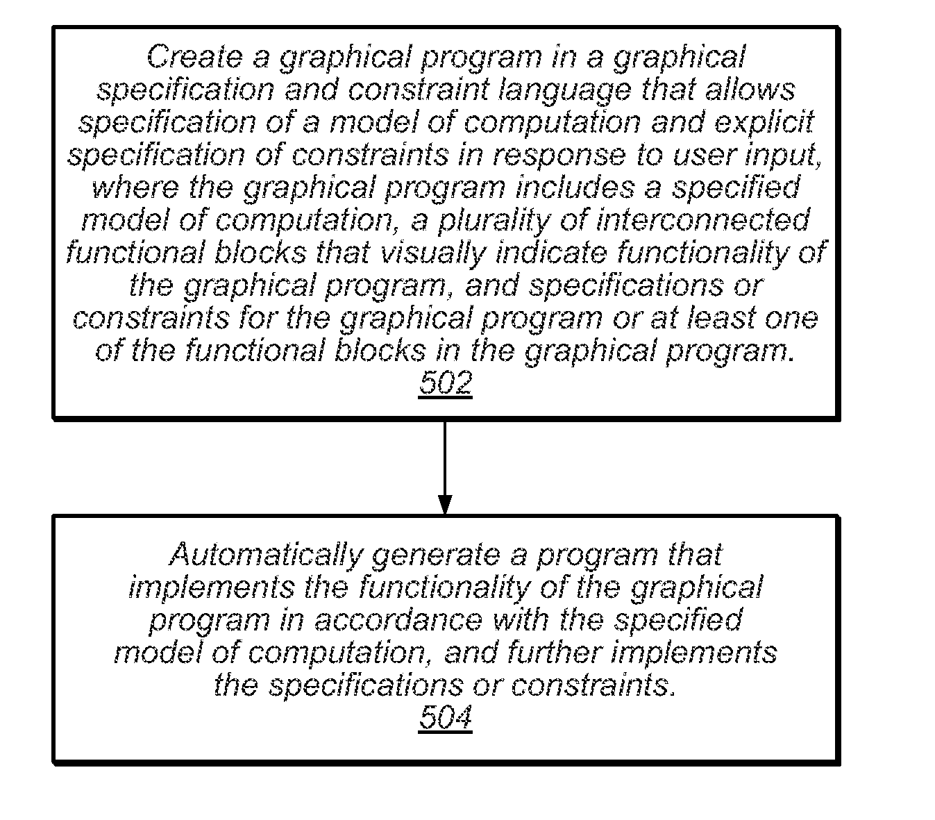
When compiling high-level, graphical code (e.g. LabVIEW™ code) to a different representation (e.g. different software code or hardware FPGA), information relating to characteristics of the design may be collected / captured from the compilation process, and automatically provided to all the earlier stages of the compilation process to obtain more optimal results. Without automated feedback of this information, users have to manually identify, produce, and provide the feedback information, or forego the process altogether, having to assume that the tool has produced the best possible results when that may not be the case. To correct timing, failed constraints paths may be parsed and compared to delays obtained during a previous compile, and previous adjustments that didn't yield desired results may be undone. The longest delay that didn't result from an undone path may then be identified, and adjusted, and the process may be repeated until all paths are predicted to pass.

Description

FIELD OF THE INVENTION[0001]The present invention relates to the field of programming, and more particularly to a system and method for generating and debugging timing accurate simulations.DESCRIPTION OF THE RELATED ART[0002]Many industrial applications require high-performance and / or efficient implementation, such as digital signal processing (DSP) applications, for example. Moreover, such applications may be subject to various constraints, e.g., with respect to timing, resource usage, throughput, etc. For example, applications to be implemented in programmable hardware, such as a field programmable gate array (FPGA) may be subject to constraints regarding the application's footprint, i.e., area used, on the FPGA. Many high-performance applications are implemented in accordance with data flow (also referred to as “dataflow”) protocols, which facilitate parallelism, particularly in hardware implementations, such as FPGA based targets.[0003]The aforementioned applications implemented...

Claims


Application Information

Patent Timeline
Patent Type & Authority Patents(United States)
IPC IPC(8): G06F17/50G06F9/44G06F11/36G06F9/45
CPCG06F11/362G06F8/34G06F8/41G06F8/30
Inventor CORRELL, JEFFREY N.BLASIG, DUSTYN K.PETERSEN, NEWTON G.
Owner NATIONAL INSTRUMENTS
Learn More