
Optical proximity correction modeling method and system

a technology of optical proximity and modeling method, applied in the field of optical proximity correction modeling method and system, can solve problems such as diffraction-induced pattern distortion

Active Publication Date: 2015-09-08
SAMSUNG ELECTRONICS CO LTD
View PDF16 Cites 3 Cited by
  • Summary
  • Abstract
  • Description
  • Claims
  • Application Information

AI Technical Summary

Benefits of technology

The patent text describes a method and system for predicting the topography effect of a pattern stack structure using optical proximity correction (OPC). This can be useful in the manufacturing of semiconductor devices, where the pattern stack structure can affect the overall topography of the device. The technical effect of the patent text is to provide a more precise and accurate way to predict the final shape of a patterned semiconductor device, which can help to improve the manufacturing process and achieve better results.

Problems solved by technology

As the wavelength of a light source used in an exposure apparatus becomes closer to a feature size of a semiconductor device, pattern distortion may occur due to diffraction, light interference, etc.

Method used


Image

  • Optical proximity correction modeling method and system
  • Optical proximity correction modeling method and system
  • Optical proximity correction modeling method and system

Examples


Embodiment Construction

[0026]Features of the present inventive concept and methods of accomplishing the same may be understood more readily by reference to the following detailed description of exemplary embodiments and the accompanying drawings. Embodiments of the present inventive concept may, however, be embodied in many different forms and should not be construed as being limited to the embodiments set forth herein.

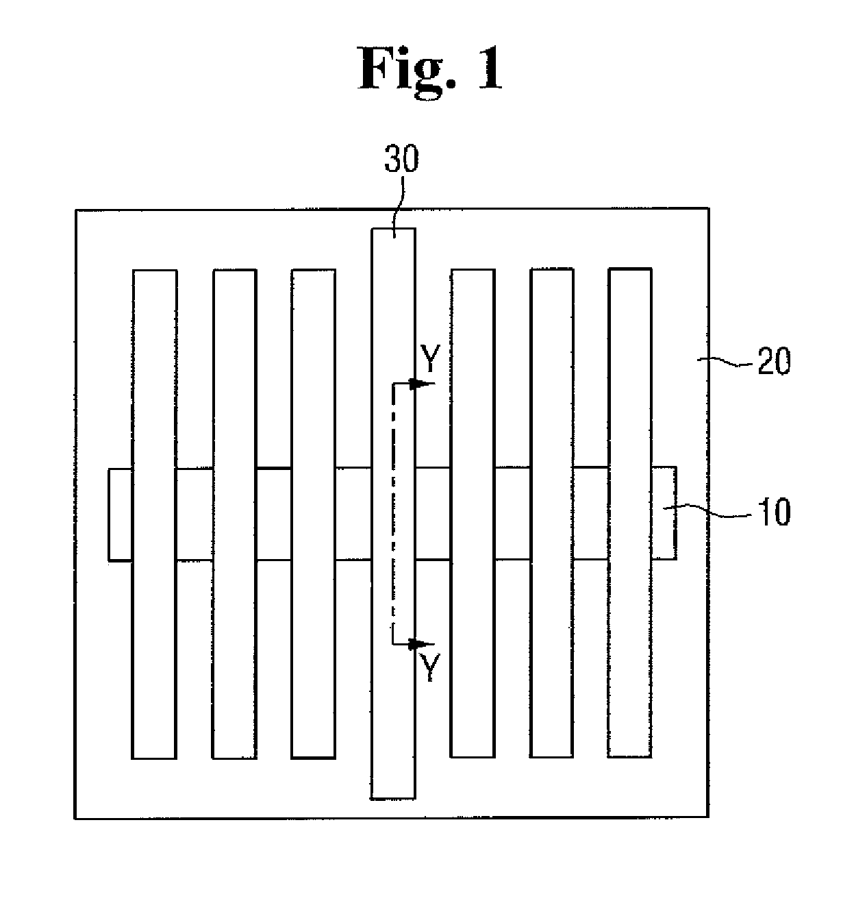
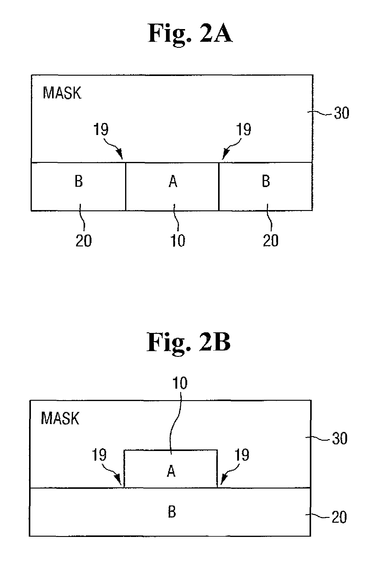
[0027]FIG. 1 is a plan view of a pattern stack structure and a mask. FIGS. 2A and 2B are cross-sectional views taken along line Y-Y of FIG. 1.

[0028]Referring to FIGS. 1, 2A and 2B, a pattern stack structure 10 and 20 is formed on a substrate. A pattern stack structure 10 and 20 is a structure formed below a mask 30 that includes two or more materials. On the other hand, a planar stack structure is a structure formed below a mask that includes only one material. As shown in FIG. 1, the pattern stack structure 10 and 20 may include, e.g., a first material pattern 10 and a second material patt...


PUM

PropertyMeasurementUnit
optical proximity correction modelingaaaaaaaaaa
reflection imageaaaaaaaaaa
reflectionaaaaaaaaaa

Abstract

An optical proximity correction modeling method for predicting a topography effect due to a pattern stack structure that includes a first material pattern, a second material pattern, and a boundary region between the first material pattern and the second material pattern. The method includes generating a first region filter that corresponds to the first material pattern, a second region filter that corresponds to the second material pattern, and an edge function corresponding to the boundary region; generating a bulk image signal from a layout using the first region filter and the second region filter; generating an edge image signal from the layout using the edge function, a characteristic kernel that represents characteristics of the boundary region, the first region filter, and the second region filter; and generating a final model signal from the bulk image signal and the edge image signal.

Description

CROSS-REFERENCE TO RELATED APPLICATION[0001]This application claims priority under 35 U.S.C. 119 from Korean Patent Application Nos. 10-2012-0095862 filed on Aug. 30, 2012 and 10-2012-0128939 filed on Nov. 14, 2012 in the Korean Intellectual Property Office, and all the benefits accruing therefrom, the contents of each of which are herein incorporated by reference in their entireties.BACKGROUND[0002]1. Technical Field[0003]The present inventive concept is directed to an optical proximity correction modeling method and system.[0004]2. Discussion of the Related Art[0005]In the design of an integrated circuit, to form a desired circuit on a semiconductor substrate, after creating a layout of the circuit, the layout may be transferred to the surface of a wafer through a photomask. As the design of the integrated circuit is complicated due to the high integration of semiconductor devices, a pattern layout should be correctly implemented according to the initially intended design on the p...

Claims


Application Information

Patent Timeline
Patent Type & Authority Patents(United States)
IPC IPC(8): G06K9/00G06T7/00G03F7/20G03F1/36
CPCG06T7/0004G03F7/70441G03F1/36
Inventor JEONG, MOON-GYU
Owner SAMSUNG ELECTRONICS CO LTD
Learn More