Method for detecting zero-field resonance
a zero-field resonance and magnetometer technology, applied in the field of paramagnetic resonance magnetometers, can solve the problems of complex and cumbersome task of precisely zeroing the magnetic field, inefficient and difficult zeroing the field using only the magnetometer signal, and inefficient and difficult zeroing the field using only the atomic signal, so as to reduce the width of the measured resonance, reduce the cost and time expenditure, and maximize the effect of heigh
- Summary
- Abstract
- Description
- Claims
- Application Information
AI Technical Summary
Benefits of technology
Problems solved by technology
Method used
Image
Examples
example 1
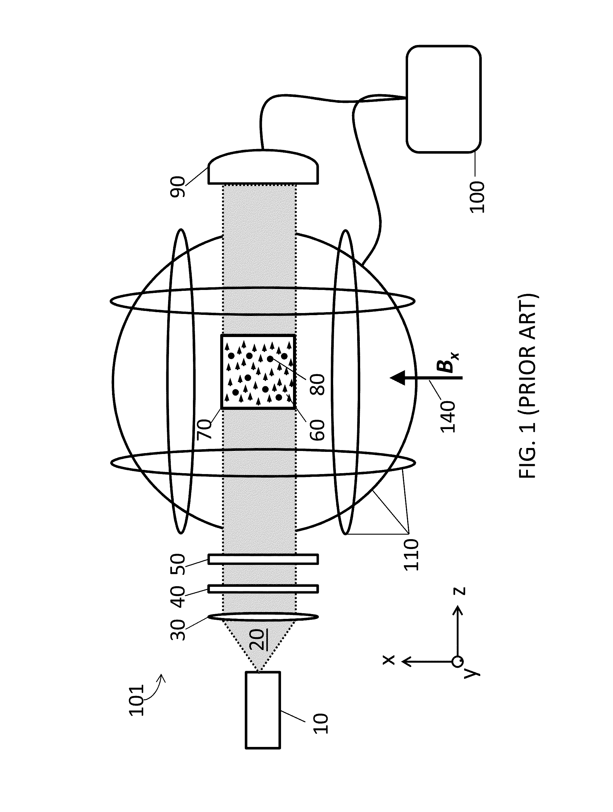
[0089]A ZF-PRM, simply referred to here as a magnetometer, was constructed in the following manner. The magnetometer housed a glass vapor cell in a shape approximating a cube having dimensions of about 4 mm)×4 mm×4 mm. The cell was vacuum processed and filled with an alkali vapor consisting of enriched rubidium-87 at a purity level exceeding 80% compared to other rubidium isotopes. Additionally, a buffer gas was added to the cell and the cell was sealed by melting the glass fill stem. The cell was mounted into a custom-built, non-metallic housing. A fiber coupled diode laser at about 795 nm was used to create a pump light beam. The diode laser was placed about 2 meters away from the magnetometer and the pump beam was delivered to the magnetometer with a polarization-maintaining, single-mode optical fiber. A lens in the magnetometer housing was used to collimate the pump beam from the optical fiber. Additional optical components such as polarizers, waveplates, and mirrors were used w...
example 2
[0091]The magnetometer described above was placed in a non-shielded, open-air environment, randomly oriented with respect to the Earth's magnetic field. Using the iterative prior art method of stepping through the bias field, we characterized the time required to find the zero-field resonance of a ZF-PRM magnetometer in this un-shielded environment. The magnetometer was oriented so that Earth's field was not substantially along the direction of the pump beam. We turned on the pump beam and did not observe a ZF resonance due to the unknown field and direction. We started our search for the ZF resonance by setting the applied z-bias field to zero and stepping through values of x-bias fields and y-bias fields. After searching through values of x-bias fields and y-bias fields, we reset the x and y values and made a small change in the z-bias field. We then began our search anew by adjusting x-bias fields and y-bias fields for that particular z value. We iterated this process for over an...
example 3
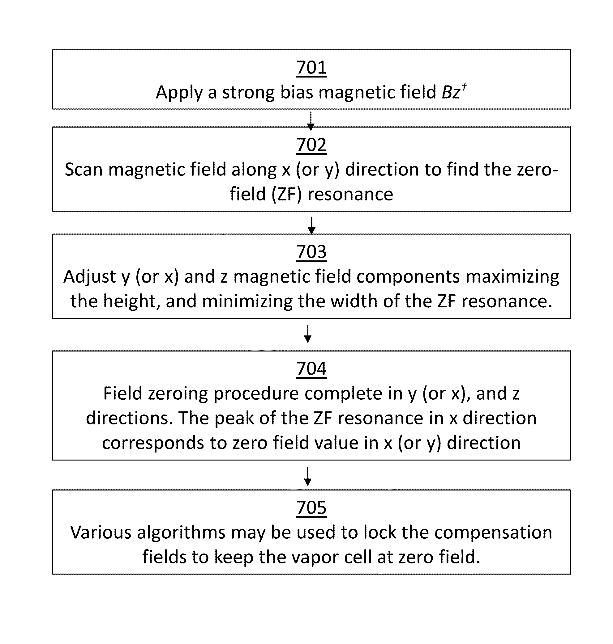
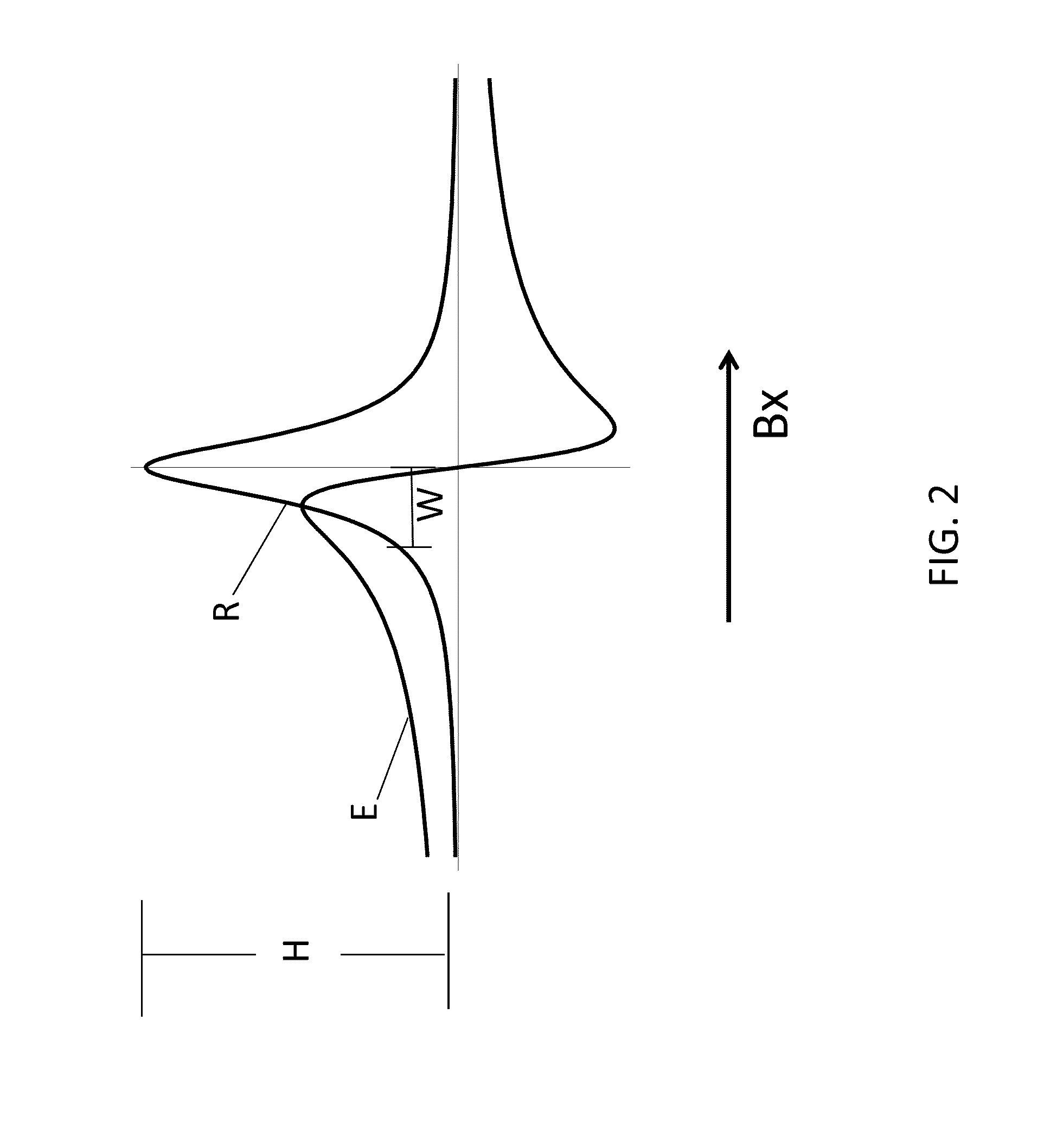
[0092]To test the efficiency and ease of use of the example magnetometer system and method of the present invention, the magnetometer, described above, was again located in an un-shielded, open air environment exposed to the Earth's magnetic field as in Example 2. As in Example 2, we oriented the magnetometer so that Earth's field was not substantially along the direction of the pump beam. We turned on the pump beam and did not observe a ZF resonance due to the unknown field and direction. Using the z-bias coils we applied a magnetic bias field, Bz, in the direction of the pump beam which is along the z-axis. The applied field had a magnitude of about 100 μT which is about twice Earth's magnetic field, or in other words about twice the maximum expected field. Immediately after applying the bias field Bz a strong transmission signal was easily observed due to the induced broadening of the resonance and the increased strength of the resonance. By scanning the current in the coil assem...
PUM
| Property | Measurement | Unit |
|---|---|---|
| magnetic fields | aaaaa | aaaaa |
| magnetic field | aaaaa | aaaaa |
| magnetic field | aaaaa | aaaaa |
Abstract
Description
Claims
Application Information
 - R&D
- Intellectual Property
- Life Sciences
- Materials
- Tech Scout
- Unparalleled Data Quality
- Higher Quality Content
- 60% Fewer Hallucinations
Browse by: Latest US Patents, China's latest patents, Technical Efficacy Thesaurus, Application Domain, Technology Topic, Popular Technical Reports.
© 2025 PatSnap. All rights reserved.Legal|Privacy policy|Modern Slavery Act Transparency Statement|Sitemap|About US| Contact US: help@patsnap.com


