
Braking-force generator

a technology of braking force and generator, which is applied in the direction of braking system, vehicle components, transportation and packaging, etc., can solve the problems of difficulty in the device itself to solve the abnormality, and the driver will feel a sense of incongruity, so as to suppress the incongruity the driver feels

Active Publication Date: 2015-08-18
HONDA MOTOR CO LTD
View PDF19 Cites 4 Cited by
  • Summary
  • Abstract
  • Description
  • Claims
  • Application Information

AI Technical Summary

Benefits of technology

[0016]According to the second aspect of the present invention, the braking-force generator can generate the braking force by the hydraulic-pressure generating means immediately after the abnormality determination means determines that the operational state of the hydraulic-pressure generating means changes from an abnormal state to a normal state. In addition, since the third braking force generated by the hydraulic-pressure generating means is weak, the braking force which the driver feels does not greatly increase, so that the sense of incongruity which the driver feels can be suppressed.
[0017]Thus, according to the present invention, it is possible to provide a braking-force generator which does not cause the driver to feel a sense of incongruity even when the braking-force generator is automatically restored from an abnormality.

Problems solved by technology

In the past, generally, when an abnormality occurs in a device such as the braking-force generator, it was difficult for the device to solve the abnormality by itself.
If the operation of the servo mechanism is restarted when the driver is not pushing the brake pedal, the braking force increases regardless of the intention of the driver, so that the driver will feel a sense of incongruity.

Method used


Image

  • Braking-force generator
  • Braking-force generator
  • Braking-force generator

Examples


first embodiment

1. First Embodiment

1.1 Outline of Structure

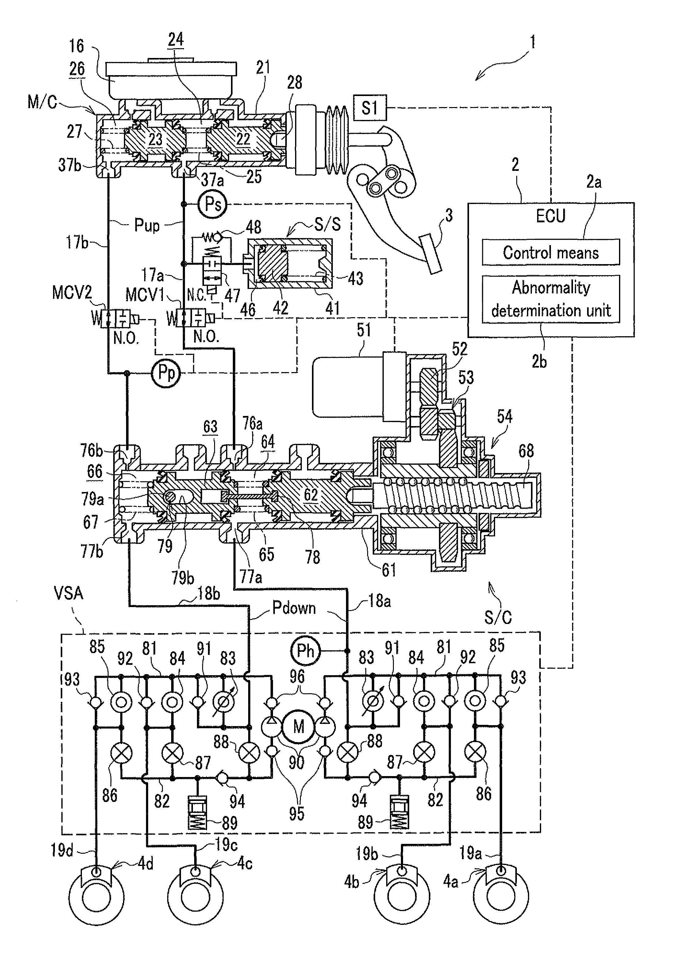
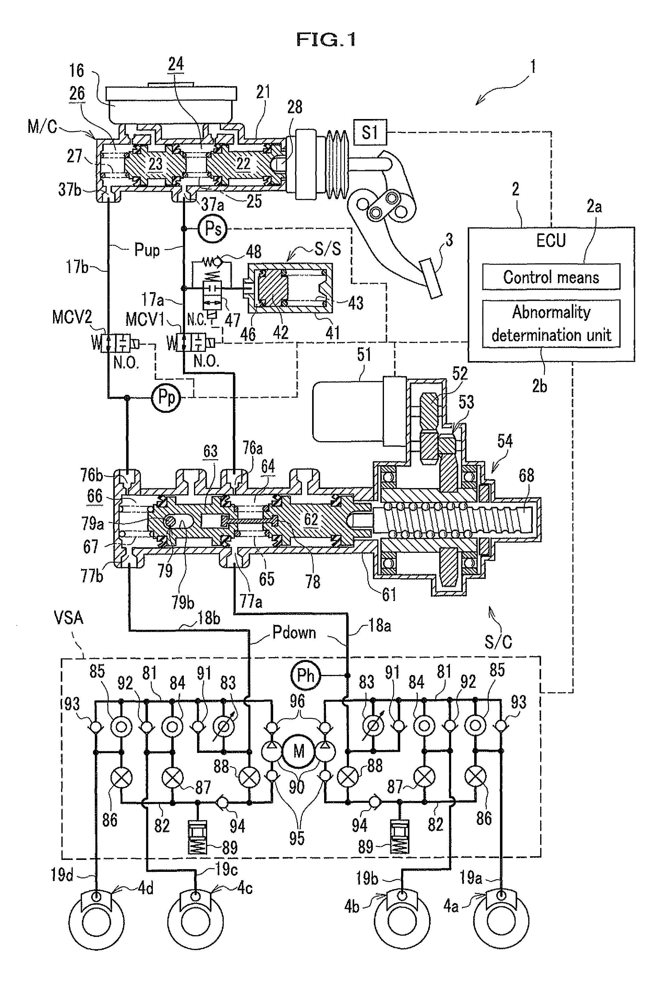
[0026]FIG. 1 is a block-diagram illustrating the braking-force generator 1 according to the first embodiment of the present invention. The braking-force generator 1 contains a brake pedal 3, wheel cylinders 4a, 4b, 4c, and 4d, a tandem-type master cylinder M / C, first hydraulic routes 17a-18a-19a and 17a-18a-19b respectively constituted by the hydraulic paths 17a, 18a, and 19a and the hydraulic paths 17a, 18a, and 19b, and second hydraulic routes 17b-18b-19c and 17b-18b-19d respectively constituted by the hydraulic paths 17b, 18b, and 19c and the hydraulic paths 17b, 18b, and 19d. The master cylinder M / C can generate hydraulic pressure by a driver's manipulation with the brake pedal 3. The hydraulic paths constituting the first hydraulic routes 17a-18a-19a and 17a-18a-19b connect a first hydraulic chamber 24 in the master cylinder M / C and the master cylinders 4a and 4b, and the hydraulic paths constituting the second hydraulic routes 17b-18b...

second embodiment

2. Second Embodiment

[0048]FIG. 4 is a flow diagram indicating a sequence of operations in a process for generating braking force according to the second embodiment of the present invention. The braking-force generator 1 according to the first embodiment can also be used in the second embodiment. However, in the second embodiment, the pump 90 in the vehicle stability assist VSA is used as a braking-force assist device having a function of a hydro-booster control (HBC) which generates auxiliary braking force. The auxiliary braking force supplements the braking force which is generated in the master cylinder M / C by the driver manipulating the brake pedal 3. In the second embodiment, the vehicle stability assist VSA functions as the aforementioned control system for stabilization of the vehicle motion when the braking-force generator 1 is normal, and does not function when the braking-force generator 1 is abnormal. Therefore, in the second embodiment, the pump 90 in the vehicle stabilit...

third embodiment

3. Third Embodiment

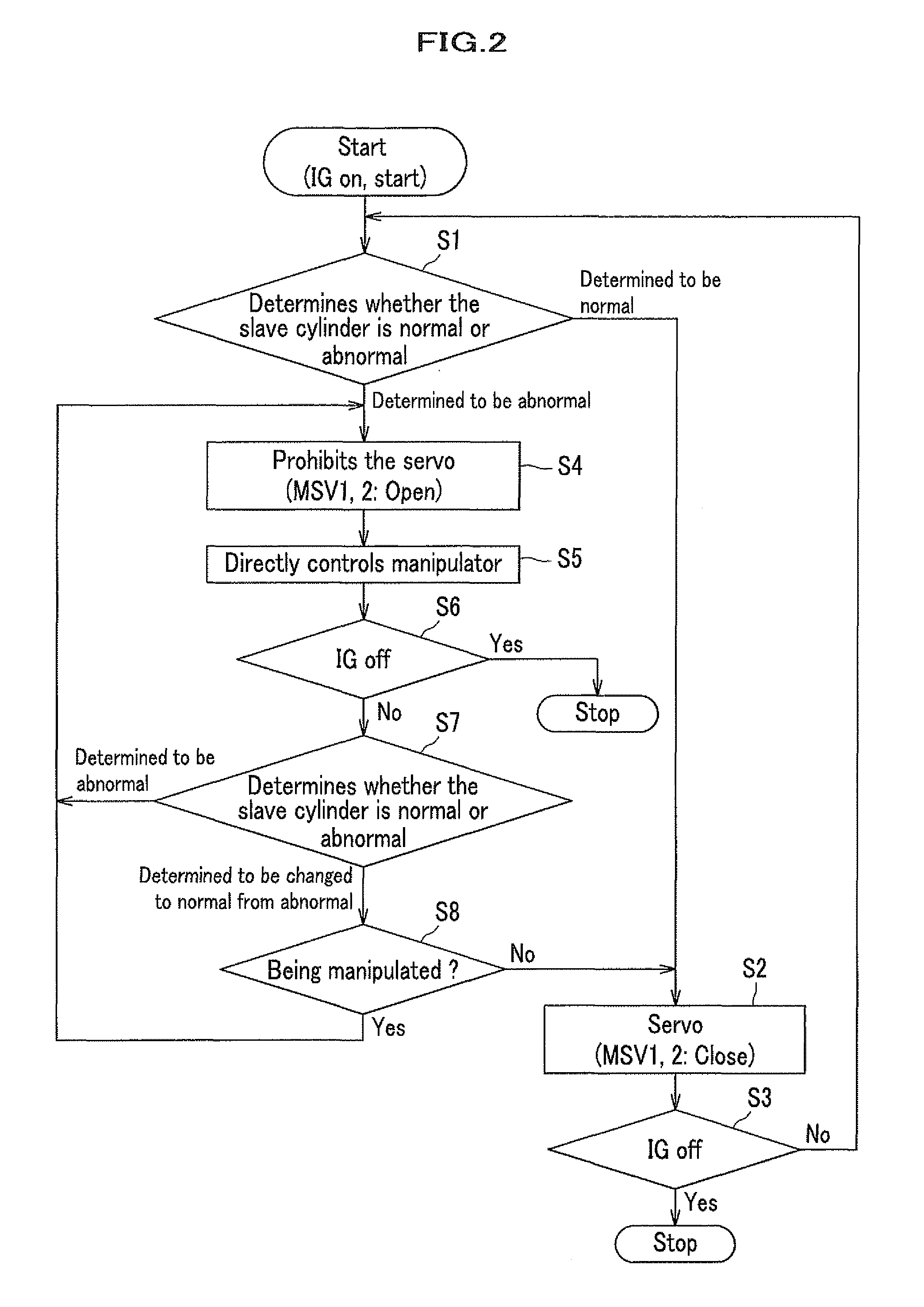
[0050]FIG. 6 is a flow diagram indicating a sequence of operations in a process for generating braking force according to the third embodiment of the present invention. The braking-force generator 1 according to the first embodiment can also be used in the third embodiment. Steps S1 to S8 in the sequence according to the third embodiment indicated in FIG. 6 are identical to steps S1 to S8 in the sequence according to the first embodiment indicated in FIG. 2. Therefore, the explanations on steps S1 to S8 are not repeated. However, the process for generating braking force in the third embodiment further includes step S9, which is performed when yes is determined in step S8.

[0051]When the determination by the abnormality determination unit 2b in step S7 changes from abnormality to normality, and the brake pedal 3 is determined in step S8 to be being manipulated (i.e., yes is determined in step S8), in step S9, the control means 2a performs a servo operation for gener...


PUM


Abstract

In a braking-force generator: a master cylinder generates first braking force corresponding to an operational input through a manipulator; a hydraulic-pressure generator connected to the master cylinder through a shutoff valve generates second braking force corresponding to the operational input through the manipulator when the shutoff valve is closed; an abnormality detector repeatedly determines whether or not an operational state of the hydraulic-pressure generator is abnormal; and a controller prohibits generation of the second braking force, opens the shutoff valve, and transmits the first braking force to the hydraulic-pressure generator, when the operational state is abnormal. In the case where the abnormality detector determines that the operational state changes from an abnormal state to a normal state while manipulation with the manipulator is being performed, the controller keeps prohibition of the generation of the second braking force and keeps the shutoff valve open until the manipulation is terminated.

Description

CROSS-REFERENCE TO RELATED APPLICATIONS[0001]This application claims the foreign priority benefit under 35 U.S.C. §119 of Japanese Patent Application No. 2012-158339, filed on Jul. 17, 2012, the disclosure of which is incorporated herein by reference.BACKGROUND OF THE INVENTION[0002]1. Field of the Invention[0003]The present invention relates to a braking-force generator which generates braking force corresponding to an electric signal generated on the basis of an operational input by an operator.[0004]2. Description of the Related Art[0005]The braking-force generator does not need direct exertion of the force produced by the driver as braking force for a vehicle, and can realize the so-called brake-by-wire (BBW) system. (See, for example, Japanese Registered Patent No. 4801823.)[0006]In the past, generally, when an abnormality occurs in a device such as the braking-force generator, it was difficult for the device to solve the abnormality by itself. However, currently, as in the typ...

Claims


Application Information

Patent Timeline
Patent Type & Authority Patents(United States)
IPC IPC(8): F15B15/00B60T13/14B60T13/66B60T13/74B60T8/40B60T8/94
CPCF15B15/00B60T8/4081B60T13/147B60T13/662B60T13/745B60T8/94
Inventor ITO, YUKI
Owner HONDA MOTOR CO LTD
Learn More