
Vehicle braking system

A technology of braking device and wheel brake cylinder, which is applied to electric devices, power devices, foot-actuated starting devices, etc., can solve the problems of increased power consumption, large-scale and unrealistic shut-off valves, etc., so as to suppress the sense of incongruity. , the effect of enhancing the feeling

Active Publication Date: 2015-04-01
HONDA MOTOR CO LTD
View PDF6 Cites 0 Cited by
  • Summary
  • Abstract
  • Description
  • Claims
  • Application Information

AI Technical Summary

Problems solved by technology

[0010] It is also conceivable to increase the thrust applied to the valve body so that the shutoff valve can always maintain the closed state, but with the increase of the thrust, power consumption increases or the shutoff valve needs to be enlarged, which is difficult when mounted on a vehicle. Unrealistic

Method used


Image

  • Vehicle braking system
  • Vehicle braking system
  • Vehicle braking system

Examples


Embodiment Construction

[0043] Hereinafter, embodiments of the present invention will be described in detail with reference to the drawings as appropriate. In addition, in each figure, the same code|symbol is attached|subjected to the common part, and the overlapping description is abbreviate|omitted.

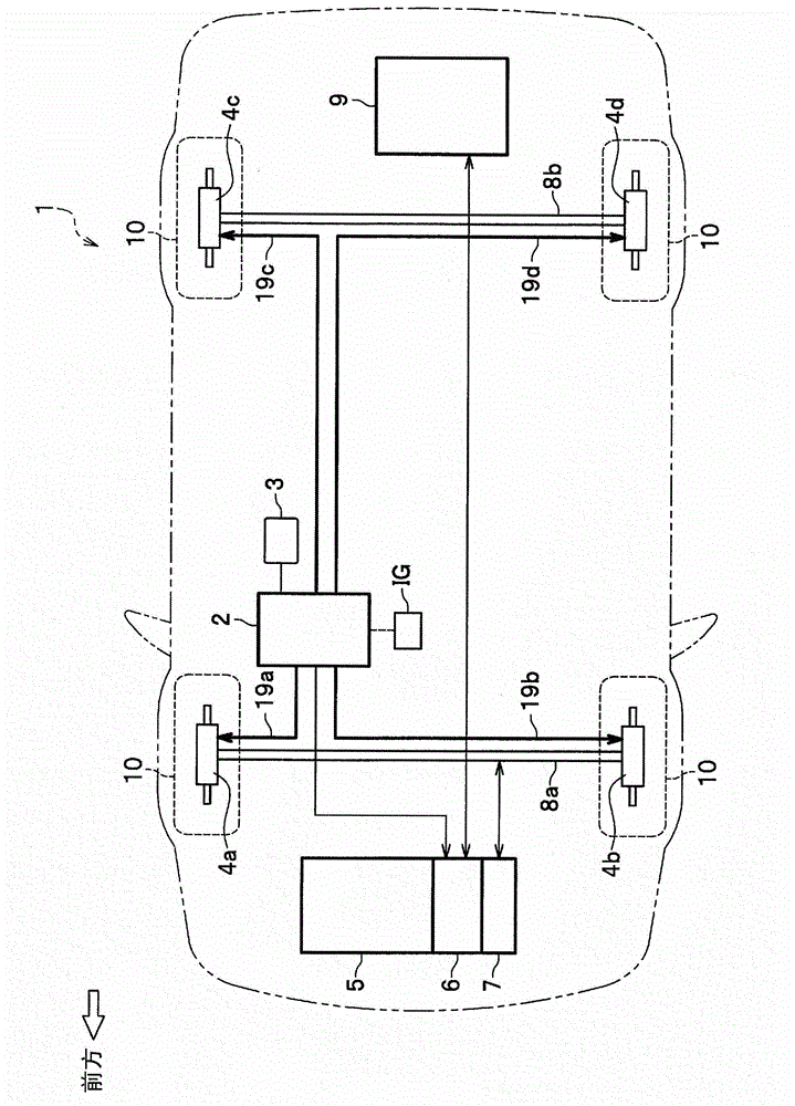
[0044] figure 1 A configuration diagram showing a vehicle 1 equipped with a vehicle brake device 2 according to an embodiment of the present invention. The vehicle 1 has four wheels 10 , the front two wheels 10 are connected to the axle 8 a, and the rear two wheels 10 are connected to the axle 8 b. The axle 8a receives driving force from at least one of the engine 5 and the motor (electric motor) 6 via the transmission 7, and transmits the driving force to the two front wheels 10 to rotate. In addition, the axle 8a transmits the rotational energy (kinetic energy) of the two front wheels 10 as regenerative energy to the transmission 7, and then to the motor (electric motor) 6, where the regenerative en...


PUM


Abstract

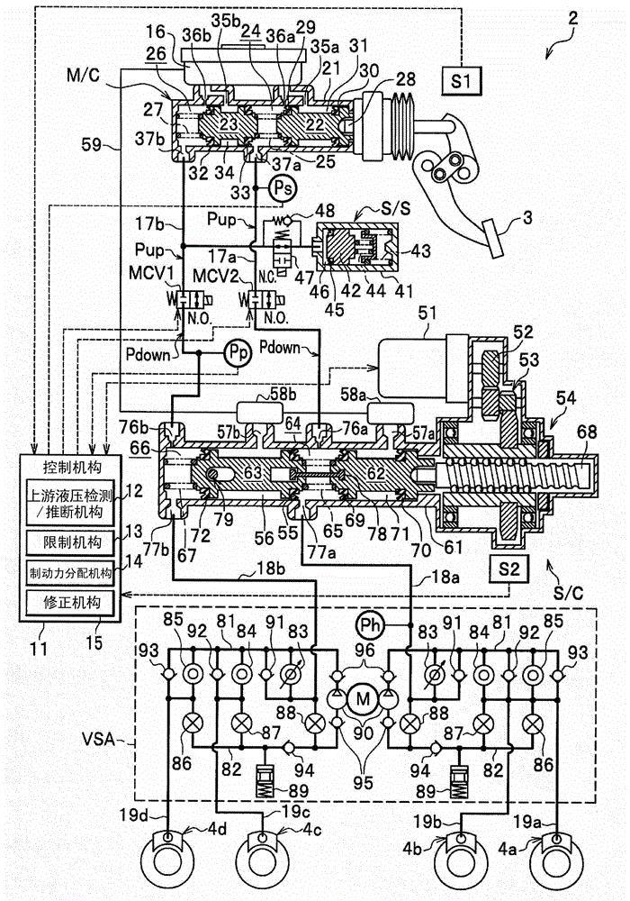
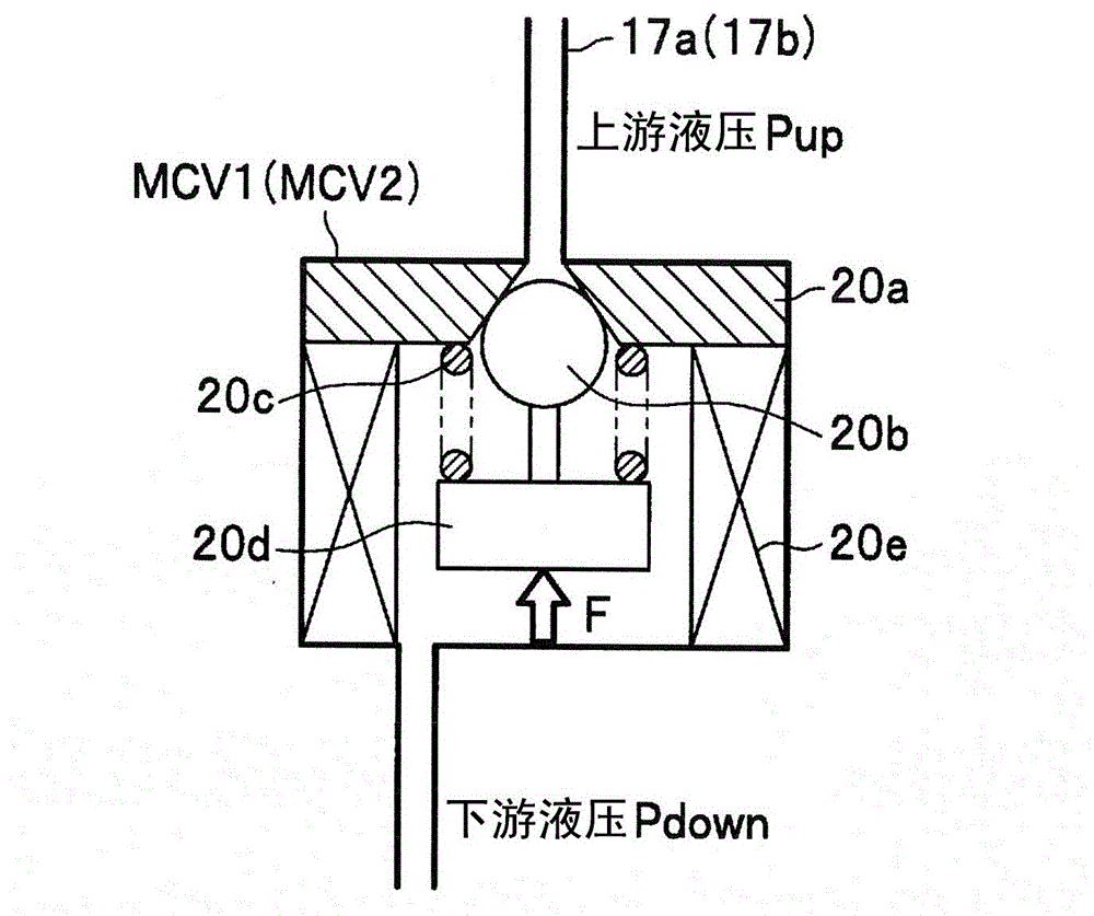
Provided is a vehicle braking system which includes a master cylinder (M / C) for producing an upstream fluid pressure (Pup) associated with a manipulation of a brake control portion (3); a shut-off valve (MCV 1) or the like which is disposed between the master cylinder (M / C) and a wheel cylinder (4a) or the like; a fluid pressure source (S / C) for producing a downstream fluid pressure (Pdown) between the shut-off valve (MCV 1) and the wheel cylinder (4a) or the like when a command for closing the shut-off valve (MCV 1) has been received; and a control means (11) for setting a target value for the downstream fluid pressure (Pdown) on the basis of the amount of the manipulation and controlling the downstream fluid pressure (Pdown) on the basis of the target value. The control means (11) includes an upstream fluid pressure detecting and estimating means (12) for detecting and estimating the upstream fluid pressure (Pup), and a restricting means (13) for restricting the difference in pressure between the upstream fluid pressure (Pup) and the target value. This allows for providing the vehicle braking system which can prevent an unfamiliar feeling, which the vehicle operator would otherwise experience while manipulating the brake, without an increase in power consumption of the shut-off valve that is disposed between the master cylinder and the wheel cylinder.

Description

technical field [0001] The present invention relates to a vehicle braking device in which a shutoff valve is provided between a master cylinder and a wheel cylinder, and a hydraulic pressure source is provided between the shutoff valve and the wheel cylinder. Background technique [0002] In a vehicle brake system, a master cylinder is connected to a wheel cylinder through a hydraulic circuit. When the driver operates the brake operating unit, upstream hydraulic pressure is generated in the master cylinder. The upstream hydraulic pressure is cut off by the shutoff valve, and the wheel cylinders are not actuated directly. Not only the operation amount of the brake operating unit but also other physical quantities are added to generate downstream hydraulic pressure at the hydraulic source, and the wheel cylinders are actuated. Such a braking method is called a so-called brake-by-wire (BBW) method, and a vehicle braking device realizing this braking method has been proposed (f...

Claims


Application Information

Patent Timeline
Patent Type & Authority Patents(China)
IPC IPC(8): B60T8/17B60T17/08B60K6/485B60L7/24B60L11/14B60T8/48B60L50/16
CPCB60T7/06B60L3/0092B60T13/745B60T8/1755Y02T10/7241B60L7/26B60L2210/40B60T2270/613B60L11/1877B60T13/586Y02T10/7005B60T2270/604Y02T10/70B60L11/14Y02T10/705B60L7/18Y02T10/7077B60T8/4081B60L50/16B60L50/66Y02T10/72Y02T10/7072
Inventor 伊藤雄贵帆谷雄辉佐藤伸一
Owner HONDA MOTOR CO LTD
Learn More