
Packet communication method and equipment therefor

a packet communication and communication method technology, applied in data switching networks, frequency-division multiplexes, instruments, etc., can solve the problem that the system is not applicable to the packet communication system, and achieve the effect of preventing or reducing the drop frame of the screen or

Inactive Publication Date: 2015-07-14
JAPAN ATOMIC ENERGY AGENCY INDEPENDANT ADMINISTRATIVE CORP
View PDF9 Cites 0 Cited by
  • Summary
  • Abstract
  • Description
  • Claims
  • Application Information

AI Technical Summary

Benefits of technology

[0008]An object of the present invention is to prevent or reduce adverse effects that will be resulted from decline in communication data quality caused by the packet loss appeared in a packet communication that uses existing network circuits.
[0009]To be more precise, the object is to provide a packet communication method and equipment therefor that are capable of preventing or reducing drop frame of screen or speech interruption that makes sound harsh attributable to loss or transmission delay of some of sound data packets or picture data packets, even though existing transmission lines are used.
[0014]The present invention realizes a packet communication method and equipment therefor that are capable of preventing or reducing drop frame of screen or speech interruption that makes sound harsh attributable to loss or delay of some of sound data packets or picture data packets, even though existing transmission lines are used.

Problems solved by technology

Therefore, such system is not applicable to a packet communication system that uses existing network circuits having transmission lines of which routers have no function for transmission route selection like mentioned above.

Method used


Image

  • Packet communication method and equipment therefor
  • Packet communication method and equipment therefor
  • Packet communication method and equipment therefor

Examples


Embodiment Construction

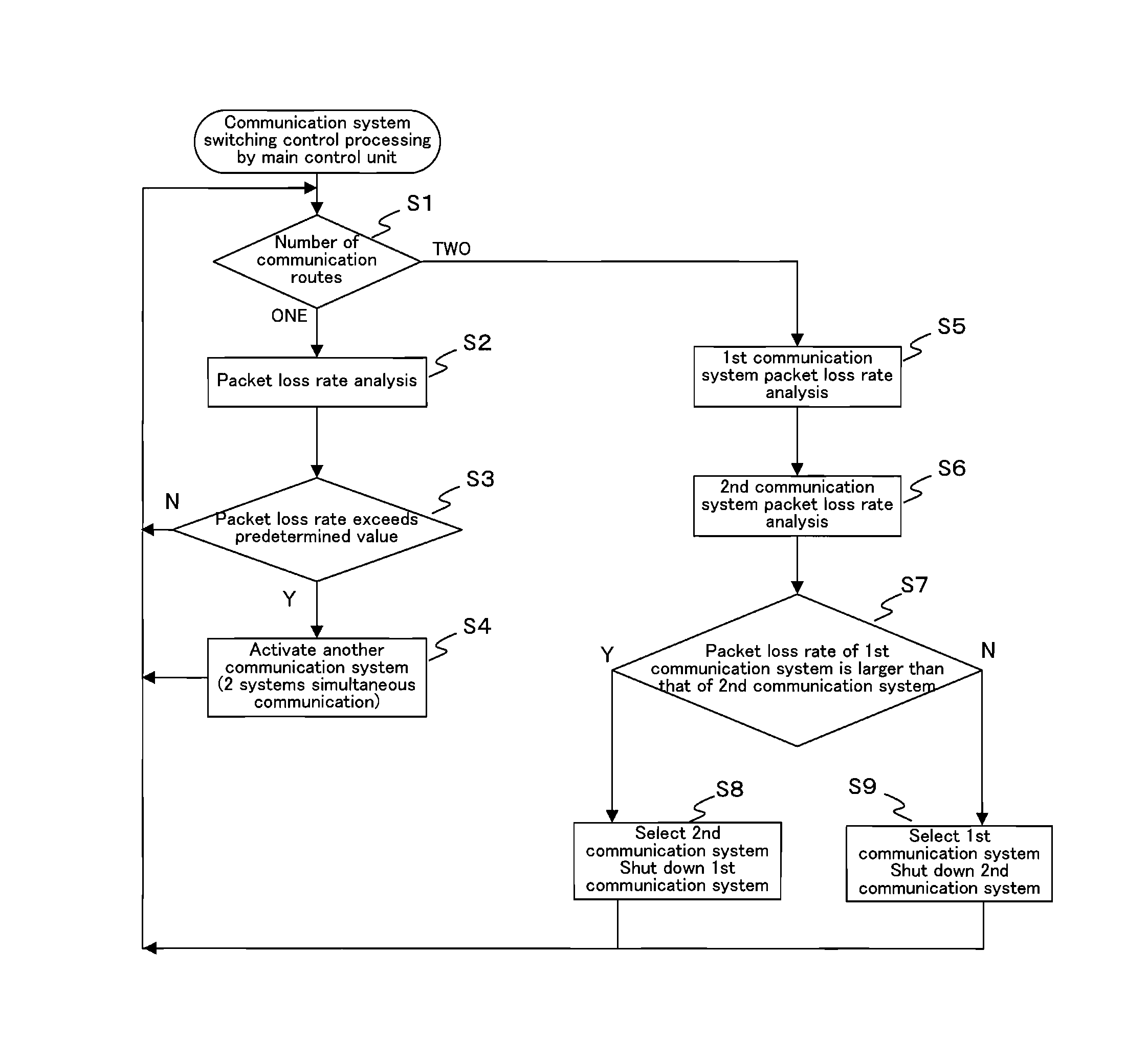
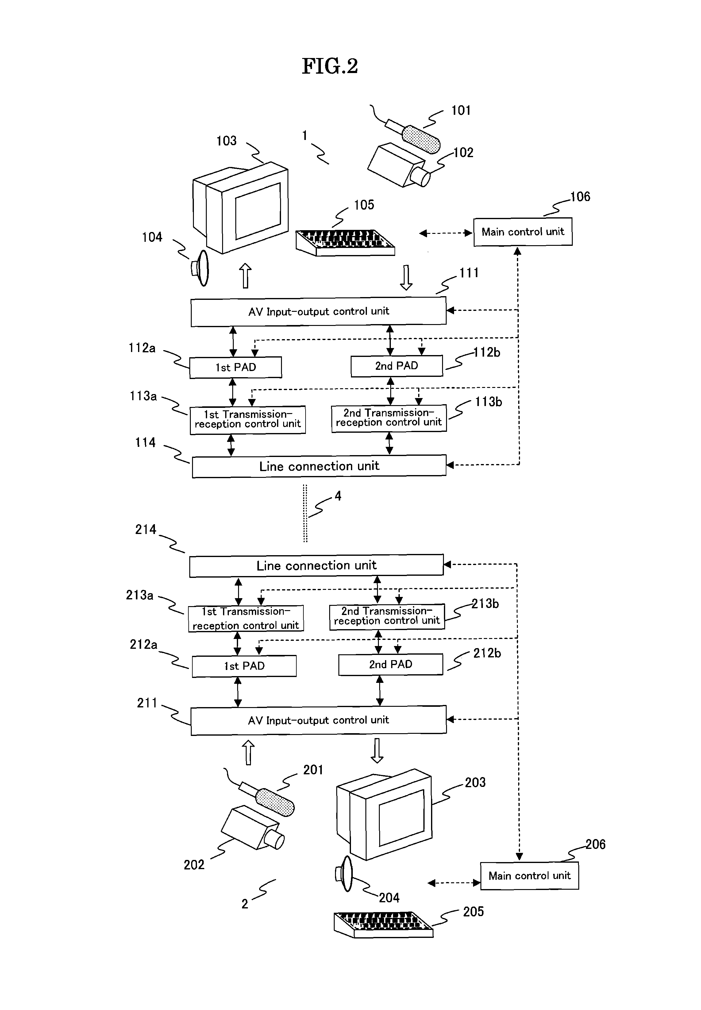
[0018]The packet communication method of the present invention is a packet communication method in which information data is packetized by a packet assembly disassembly device (a PAD) in a first terminal equipment and information data packetized thereby is transmitted therefrom; the packet data transmitted are carried through transmission lines having a plurality of transmission routes; and a second terminal equipment depacketizes the packet data received from the transmission line with a PAD to reconstruct the original information data form, wherein the first terminal equipment and the second terminal equipment have a plurality of transmitter-receiver units; the packet communication (a first packet communication) is performed using one transmitter-receiver unit in such plurality of transmitter-receiver units; if packet loss of received data in such packet communication is detected exceeding a predetermined value, a request is sent using another transmitter-receiver unit to the firs...


PUM


Abstract

To reduce or prevent effect of deterioration of communication quality caused from packet loss in a packet communication, a plurality of Packet Assembly Disassembly devices (PDAs) are installed at a first terminal equipment and at a second terminal equipment, and a packet communication is performed using one PDA in such plurality of PDAs. If the packet loss of received data in such packet communication is detected exceeding the predetermined value, a request is sent using another PDA to the first terminal equipment for transmitting the same data that above-stated one PDA is handling and the data transmitted at the request is received. On reception of the data at the request, sizes of the packet loss rate of received data with above-stated one PDA and of the packet loss rate of received data with above-stated another PDA are compared and the packet communication is continued selecting a system of which packet loss rate is smaller.

Description

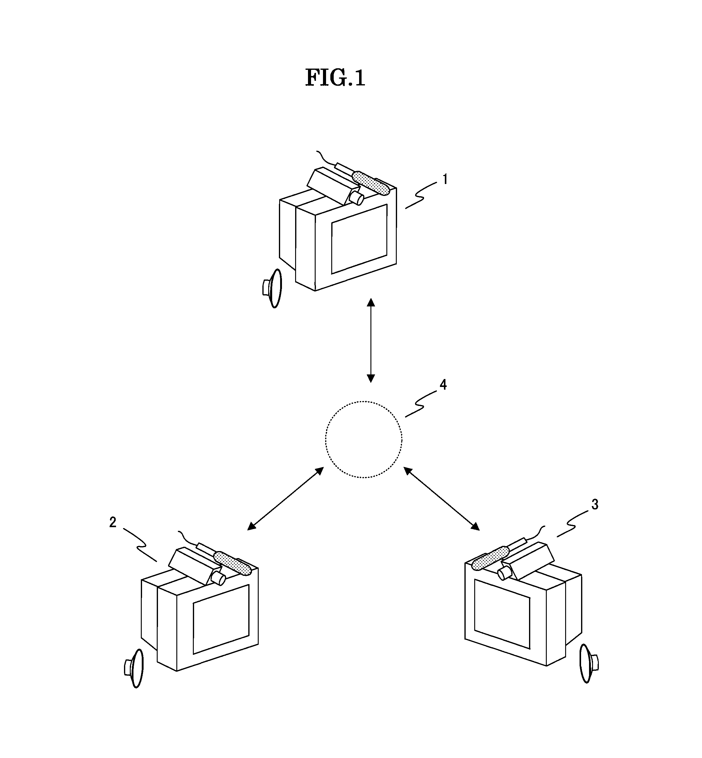
[0001]This application is drafted quoting the entire contents of the specification, drawings, and the abstract included in Japanese Patent Application No. 2011-234702 filed on Oct. 26, 2011.TECHNICAL FIELD[0002]The present invention relates to a packet communication method that works on network circuits and equipment therefor.BACKGROUND ART[0003]Internet Protocol (IP) telephone systems, IP video conference systems, or other similar systems, in which sound data and picture data are transmitted (in a form of packet communication) using network circuits, have adopted the User Datagram Protocol (UDP) communication, because such systems need the securing of continuous communication band.[0004]The UDP communication however will lose excess packets if communication information is inputted beyond the transmission capacity of transmission lines.[0005]In a video conference system working on a packet communication, loss of some of picture data packets will cause drop frame of screen and loss o...

Claims


Application Information

Patent Timeline
Patent Type & Authority Patents(United States)
IPC IPC(8): H04L1/00H04L12/26H04L29/06H04L1/06H04L45/24
CPCH04L43/0829H04L1/06H04L29/06H04L69/14H04L9/40
Inventor YAMAMOTO, YUZO
Owner JAPAN ATOMIC ENERGY AGENCY INDEPENDANT ADMINISTRATIVE CORP
Learn More