
Wire electric discharge machine for taper-machining tilted workpiece

a technology of electric discharge machine and taper machining, which is applied in the direction of computer control, program control, instruments, etc., can solve the problems of not being able to correct a coordinate system or a command value for machining, and the above countermeasure is unnecessary, so as to prevent or reduce the adverse effect of taper machining and avoid the effect of conventional adverse effects of taper machining

Active Publication Date: 2018-08-14
FANUC LTD
View PDF21 Cites 0 Cited by
  • Summary
  • Abstract
  • Description
  • Claims
  • Application Information

AI Technical Summary

Benefits of technology

The present invention provides a wire electric discharge machine capable of performing taper machining in a way that prevents or reduces adverse effects. This is achieved by controlling the position of the wire electrode so that it is perpendicular to the workpiece surface during the machining. By doing so, conventional adverse effects in taper machining can be avoided.

Problems solved by technology

Therefore, the above countermeasure is unnecessary if the wire electrode is stretched perpendicular to the table surface.
Since the workpiece itself moves around the rotary axis, however, this technique is not designed to correct a coordinate system or a command value for machining in accordance with the tilt of the workpiece.
This technique is not designed to deliberately tilt the workpiece to be taper-machined so that the wire electrode extends substantially perpendicular to a table surface.
(I) The machining speed cannot be increased due to difficulty in discharging sludge.
(II) The wire guide applies frictional force to the wire electrode, thereby adversely affecting the machining accuracy (surface roughness).
(III) Since supporting points of the wire electrode bent by the wire guide vary depending on the shape precision and machining state of the wire guide, high-precision machining is difficult.
(IV) It is difficult to set machining conditions.
Accordingly, electric discharge machining conditions must be eased, so that machining cannot be performed at high speed.
(II) The wire guide applies frictional force to the wire electrode, thereby adversely affecting the machining accuracy (surface roughness):
However, frictional force produced between the wire electrode 4 and the wire guide portion still cannot be completely eliminated.
If the wire guide of this type is used, the wire electrode 4 cannot be easily bent, so that its vibration cannot be suppressed, and hence, the electric discharge machining is unstable.
In this case, however, supporting points are subject to a large error, which is a substantial problem, as described later.
(III) Since supporting points of the wire electrode bent by the wire guide vary depending on the shape precision and machining state of the wire guide, high-precision machining is difficult:
In this case, however, a supporting point error occurs causing a great problem regarding precision. FIG. 10 is a diagram illustrating a supporting point error produced in the wire guide with a large curvature radius.
(IV) It is difficult to set machining conditions:
Since the sludge discharge efficiency varies depending on the taper angle, however, it is actually very difficult to adjust the degree to which the machining conditions are eased for the angle concerned.
The greater the taper angle, the more prominent these problems tend to be.

Method used


Image

  • Wire electric discharge machine for taper-machining tilted workpiece
  • Wire electric discharge machine for taper-machining tilted workpiece
  • Wire electric discharge machine for taper-machining tilted workpiece

Examples


first embodiment

[0140]FIG. 22 is a flowchart illustrating taper machining processing executed by the numerical controller shown in FIG. 21. The workpiece is assumed to be previously set and fixed obliquely.

[0141][Step SA01] One block of the machining program is read.

[0142][Step SA02] It is determined whether or not the read block is one that enables the coordinate system transformation function. If the block is determined to be such one, the program proceeds to Step SA03. If not, the program proceeds to Step SA11.

[0143][Step SA03] A coordinate system for taper machining is arranged with a commanded coordinate system tilt angle.

[0144][Step SA04] One block of the machining program is read.

[0145][Step SA05] It is determined whether or not the taper machining is enabled. If the taper machining is enabled, the program proceeds to Step SA06. If not, the program proceeds to Step SA09. If M15 is described in the read block in Step SA05, it is determined that the taper machining is enabled. M15 is previousl...

second embodiment

[0160]FIG. 24 is a flowchart illustrating the taper machining processing executed by the numerical controller shown in FIG. 21. Various steps of operation will be described with reference to FIG. 23. This flowchart is based on a machining program including a block that enables the coordinate system transformation function.

[0161][Step SB01] The tilt of the workpiece is set by, for example, means shown in FIG. 20.

[0162][Step SB02] A direction perpendicular to the tilted workpiece is determined by calculation.

[0163][Step SB03] The current tilt of the wire electrode is stored. According to the operation mode of the wire electric discharge machine shown in FIG. 23, the current tilt of the wire electrode is equal to the commanded taper angle.

[0164][Step SB04] One block is read.

[0165][Step SB05] It is determined whether or not the wire electrode tilt command is included in the read block. If the tilt command is included, the program proceeds to Step SB06. If not, the program proceeds to St...


PUM

PropertyMeasurementUnit
tilt angleaaaaaaaaaa

Abstract

In a wire electric discharge machine, a workpiece mounting unit mounts a workpiece tilted at a preset angle to a plane based on two orthogonal axes, X- and Y-axes. An XY-coordinate system is tilted at the preset angle so that it is transformed into an X′Y′-coordinate system. A machining command value commanded by a machining program is corrected based on the X′Y′-coordinate system. Thus, the tilted workpiece is taper-machined with a wire electrode kept substantially perpendicular to the XY-plane (table surface).

Description

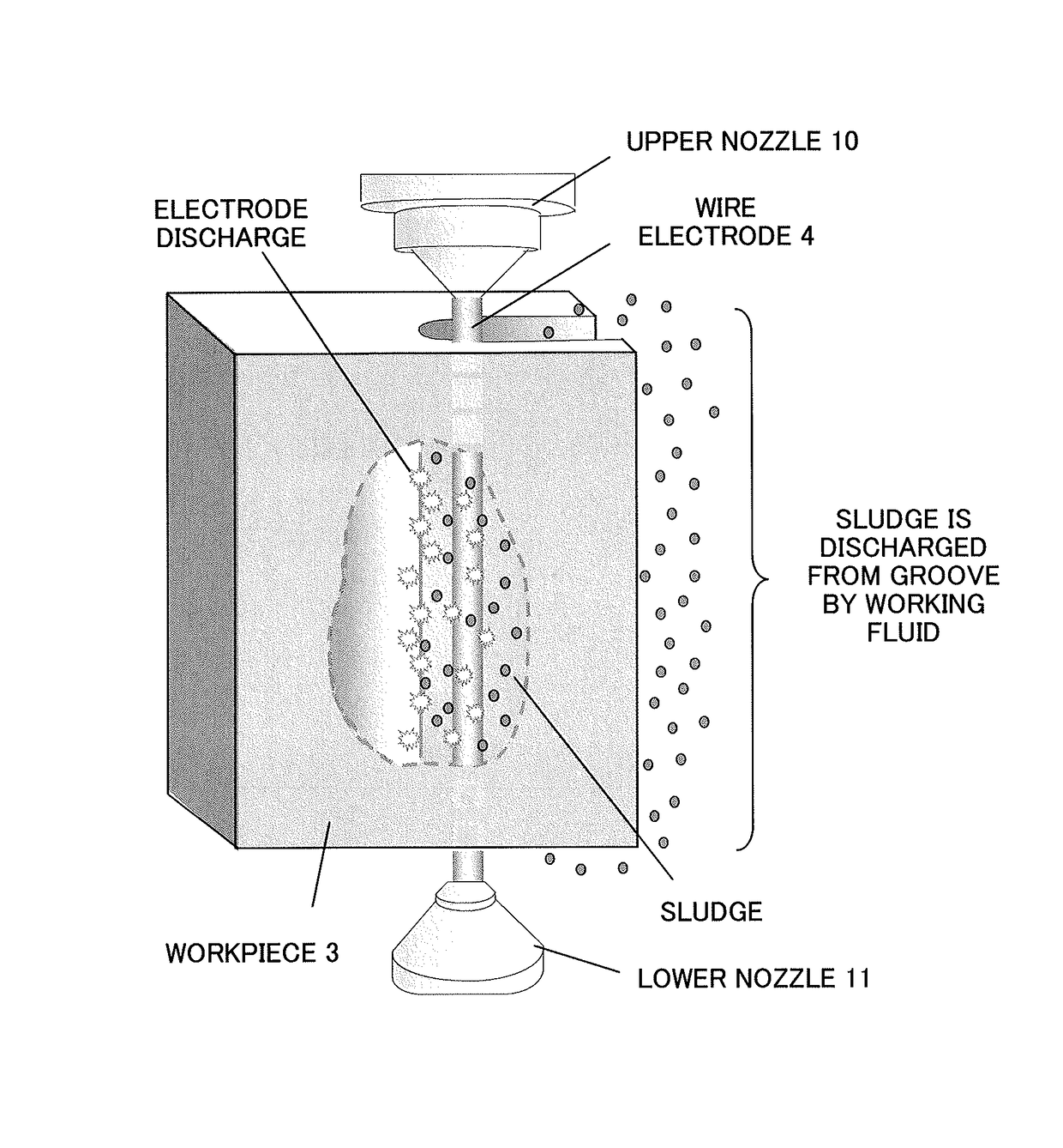
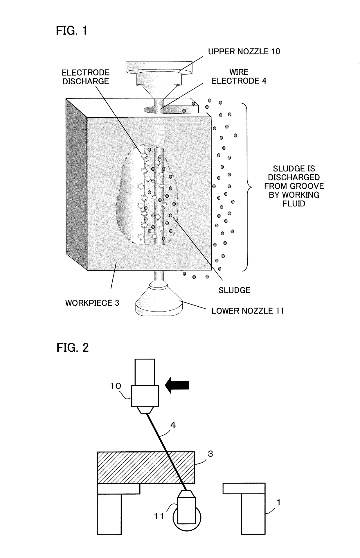
RELATED APPLICATIONS[0001]The present application is based on, and claims priority from, Japanese Application Number 2011-129764, filed Jun. 10, 2011, the disclosure of which is hereby incorporated by reference herein in its entirety.BACKGROUND OF THE INVENTION[0002]Field of the Invention[0003]The present invention relates to a wire electric discharge machine, and more particularly, to a wire electric discharge machine for taper-machining a tilted workpiece.[0004]Description of the Related Art[0005]In a conventional machining method using a wire electric discharge machine, as shown in FIG. 1, a voltage is applied to a wire electrode 4 stretched between an upper wire guide 12 in an upper nozzle 10 and a lower wire guide 13 in a lower nozzle 11, and a workpiece 3 fixed on a workpiece table 1, which is driven relative to the wire electrode 4, is moved along two axes, X- and Y-axes (not shown), which perpendicularly intersect each other on a horizontal plane. Grooving is performed to ob...

Claims


Application Information

Patent Timeline
Patent Type & Authority Patents(United States)
IPC IPC(8): B23H1/00B23H7/20G05B19/408B23H7/06B23H11/00
CPCB23H7/20B23H7/06G05B19/4086G05B2219/33263B23H1/00B23H11/003
Inventor ARAKAWA, YASUOHIRAGA, KAORUTUBOGUCHI, YUJI
Owner FANUC LTD
Learn More