
Ultraviolet laser zoom beam expanding system and laser processing equipment

Active Publication Date: 2015-06-30
HANS LASER TECH IND GRP CO LTD
View PDF3 Cites 1 Cited by
  • Summary
  • Abstract
  • Description
  • Claims
  • Application Information

AI Technical Summary

Benefits of technology

This patent describes an expanding system that uses a special lens configuration to magnify ultraviolet laser beams. The system can accommodate lasers with different diameters and light divergence angles, making it more versatile and efficient in laser processing. Compared to conventional beam expanders, the system has better shaping effects and improved focusing performance, resulting in improved processing precision and efficiency. Overall, the expanding system increases the scope and accuracy of laser processing equipment.

Problems solved by technology

According to the Rayleigh disk formula: δ=2.44λ / D, where δ represents a diameter of the Rayleigh disk, D represents an entrance pupil diameter, f represents a focal length, it can be inferred that, the smaller D, the greater δ, the power on the focus point is weaker, thus greatly reducing a processing accuracy of the system.
In the event when a greater zoom value is required, a beam expander with fixed magnification must be used, such that a requirement of multiple zoom values cannot be achieved by merely a single beam expander, which is inconvenience for laser processing and affects the efficiency of laser processing.

Method used


Image

  • Ultraviolet laser zoom beam expanding system and laser processing equipment
  • Ultraviolet laser zoom beam expanding system and laser processing equipment
  • Ultraviolet laser zoom beam expanding system and laser processing equipment

Examples


Embodiment Construction

[0022]These and other features of the present invention will become readily apparent upon further review of the following specification and drawings. The various embodiments of the invention may, however, be embodied in many different forms and should not be construed as limited to the embodiments set forth herein.

[0023]The following detailed description refers to the accompanying drawings that show, by way of illustration, specific details and embodiments in which the invention may be practiced.

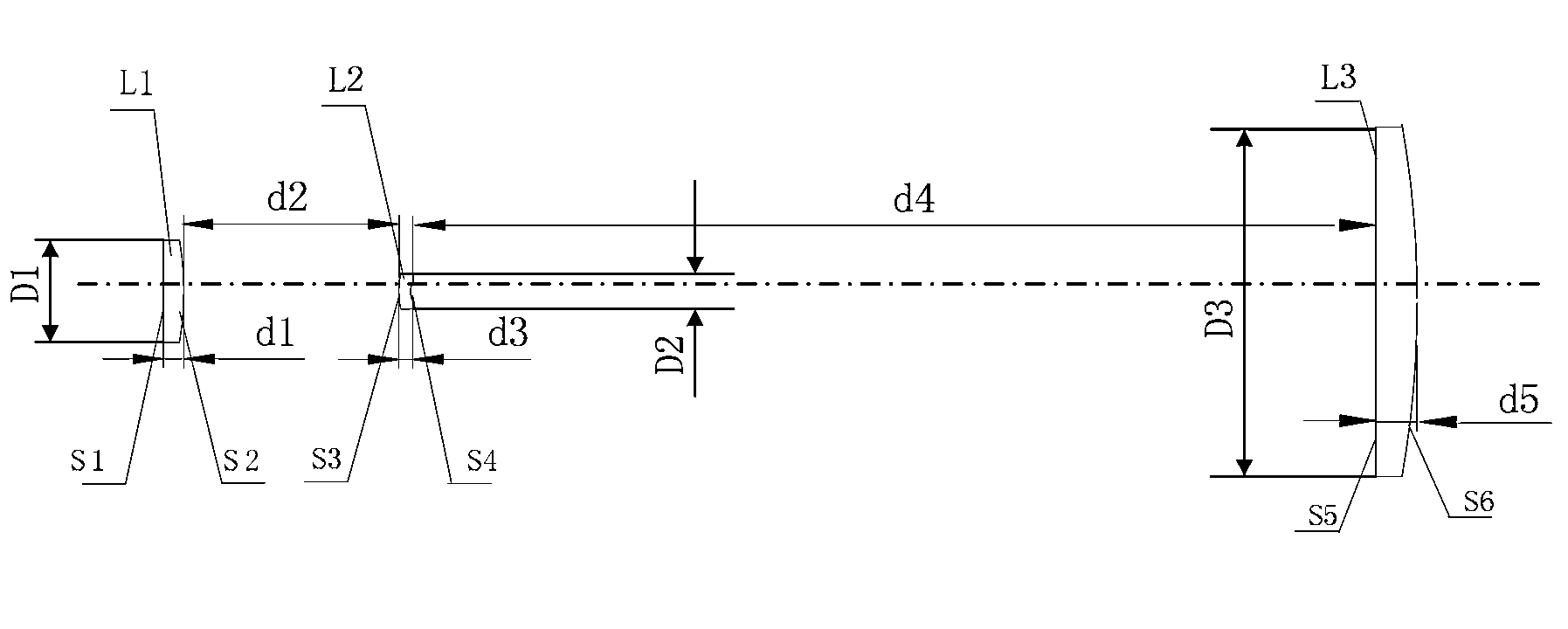
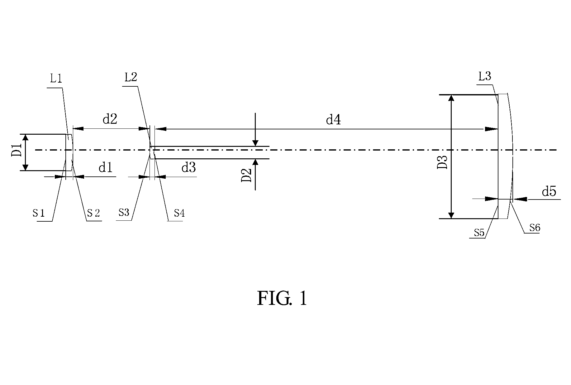
[0024]FIG. 1 shows a cross-sectional view of an ultraviolet laser zoom beam expanding system according to an embodiment of the present invention. In order to facilitate illustration, FIG. 1 merely shows a portion of ultraviolet laser zoom beam expanding system related to the embodiment.

[0025]The ultraviolet laser zoom beam expanding system is mainly applied to ultraviolet light, especially the ultraviolet light with wave length of 355 nm. Referring to FIG. 1, the system includes a first lens...


PUM


Abstract

An ultraviolet laser zoom beam expanding system, applied to the field of laser processing, includes a first lens, a second lens, and a third lens (L1, L2, L3). The first lens and the third lens (L1, L3) are plane-convex plus lenses, and the second lens (L2) is a convex-concave minus lens. The first lens, the second lens and the third lens (L1, L2, L3) respectively comprise a first surface and a second surface (S1, S2), a third surface and a fourth surface (S3, S4) as well as a fifth surface and a sixth surface (S5, S6). The radiuses of curvature of the first to sixth surfaces (S1, S2, S3, S4, S5, S6) are ∞, −30, 10, 2.2, ∞, −81. The center thickness of the first to third lenses (L1, L2, L3) is 2, 1, 4. The outer diameters of the first to third lenses (L1, L2, L3) are 10, 3, 34. Proportions of the refractive indexes to the abbe numbers of the first to third lenses (L1, L2, L3) are 1.57:41, 1.48:68, and 1.57:41. An interval (d2) between the second surface and the third surface (S2, S3) is 6-37. An interval (d4) between the fourth surface and the fifth surface (S4, S5) is 114-125, a unit is mm, and a tolerance is 5%. The system may perform beam expanding on entering light by 2-16 times, which may be adaptable to laser devices with different emergent diameters and divergence angles, and improve efficiency and accuracy of laser processing.

Description

RELATED APPLICATIONS[0001]This application is a national stage application (under 35 U.S.C. §371) of PCT / CN2013 / 077734, filed Jun. 24, 2013, which claims benefit of Chinese Application No. 201210248607.2, filed Jul. 18, 2012, the contents of which are incorporated by reference herein in its entirety.FIELD OF THE INVENTION[0002]The present disclosure relates to the field of laser processing technology, and more particularly relates to an ultraviolet laser zoom beam expanding system and a laser processing equipment.BACKGROUND OF THE INVENTION[0003]In laser processing field, the emergent light diameter Φ of a laser beam is relative small (about 1 mm). If such narrow light beam is focused directly, a greater Rayleigh disk will be obtained. According to the Rayleigh disk formula: δ=2.44λ / D, where δ represents a diameter of the Rayleigh disk, D represents an entrance pupil diameter, f represents a focal length, it can be inferred that, the smaller D, the greater δ, the power on the focus ...

Claims


Application Information

Patent Timeline
IPC IPC(8): G02B13/14G02B27/09
CPCG02B27/0955G02B19/0014G02B19/0095
Inventor LI, JIAYINGZHOU, CHAOMINGSUN, BOCHEN, YUQINGGAO, YUNFENG
Owner HANS LASER TECH IND GRP CO LTD
Learn More