
Tube-side sequentially pulsable-flow shell-and-tube heat exchanger appratus, system, and method

a heat exchanger and sequential pulsable flow technology, applied in indirect heat exchangers, chemical/physical/physicochemical processes, and tube reactors, etc., can solve the problems of increased likelihood of heterogeneous materials, work by, and lack of pulsed flow capability of shell and coil heat exchangers, etc., to improve heat exchange rates, reduce fouling, and improve heat exchange rates

Active Publication Date: 2015-06-30
DOW GLOBAL TECH LLC
View PDF27 Cites 11 Cited by
  • Summary
  • Abstract
  • Description
  • Claims
  • Application Information

AI Technical Summary

Benefits of technology

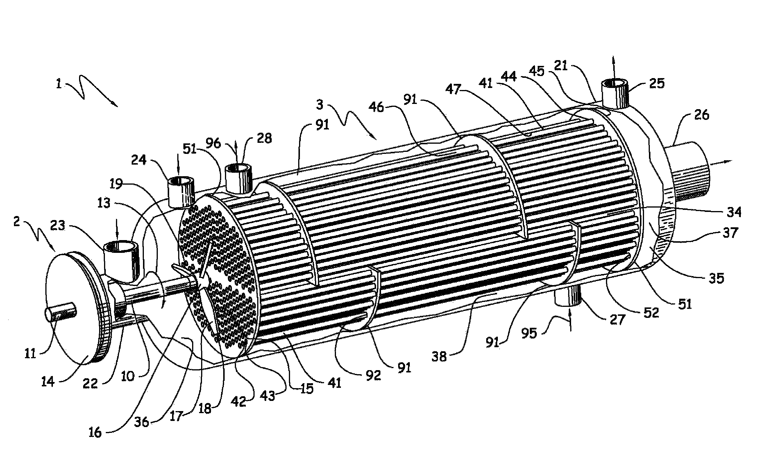
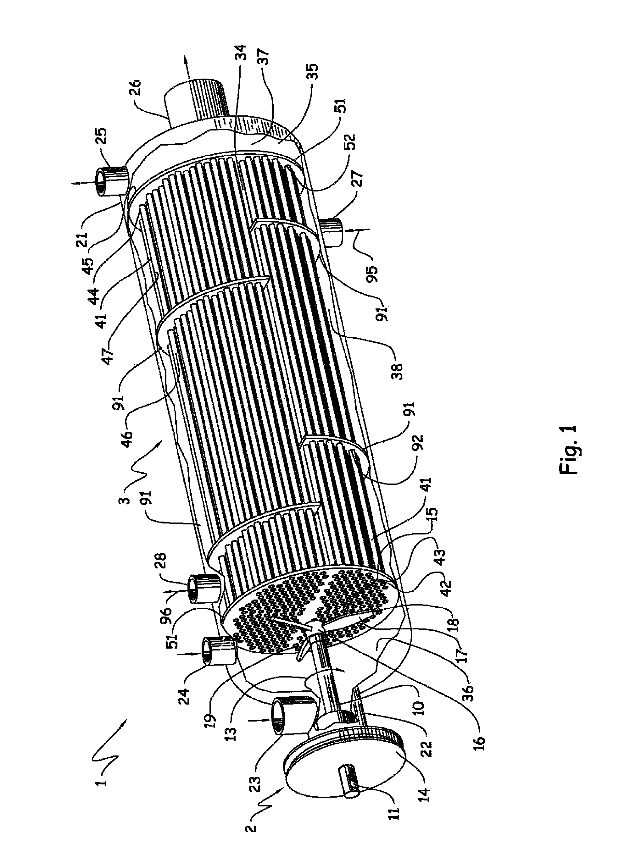
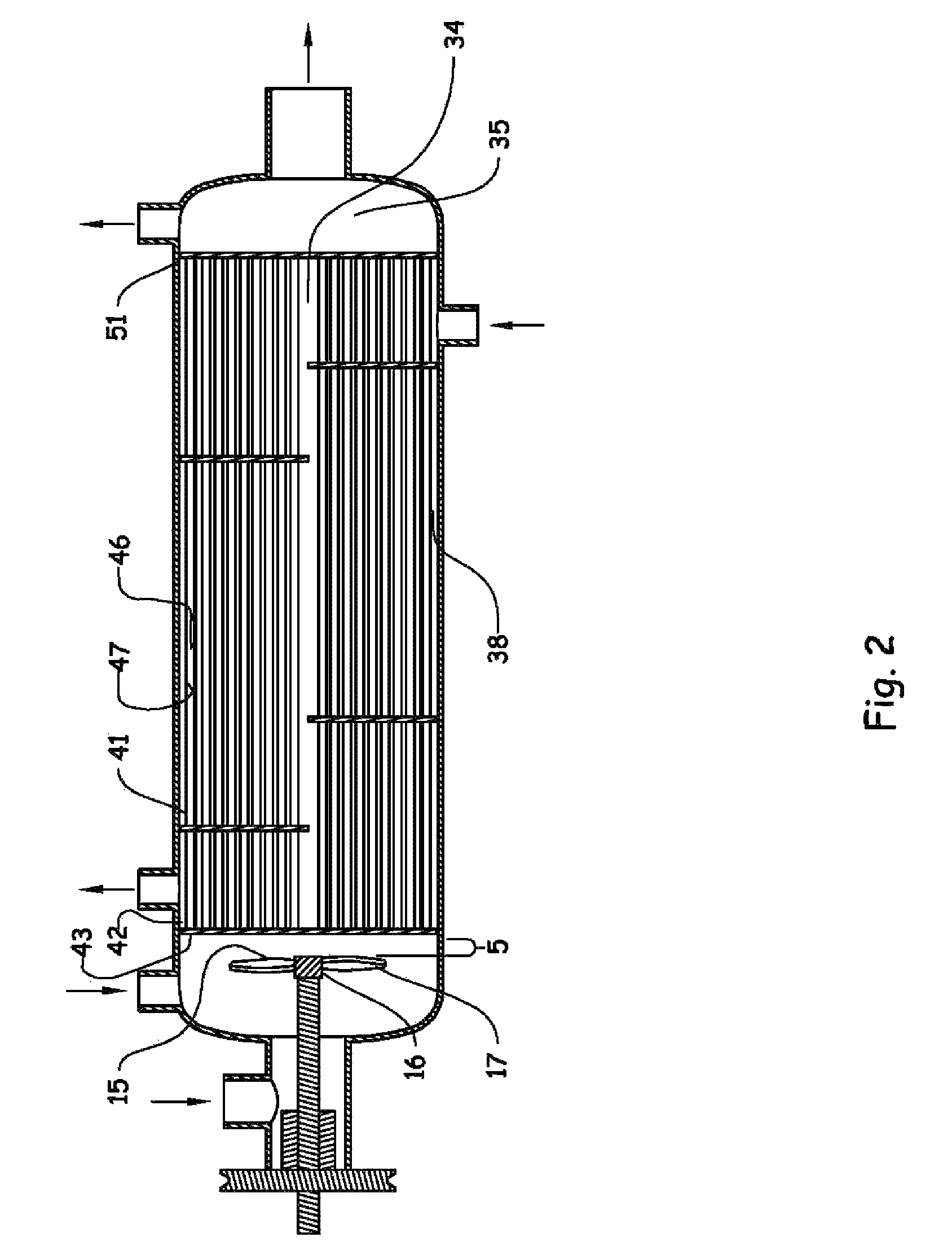
The present invention provides a heat exchanger apparatus that uses sequential puling of liquids to improve heat exchange rates and decrease fouling of tubes, especially when using fouling-prone process fluids. The apparatus maintains an average flow rate of the process fluid and only locally varies flow rates of the process fluid in the tubes. The pulsing of flow may inhibit agglomeration and deagglomeration of solid particles in the inlet plenum and outlet plenum, respectively. Overall, the heat exchanger apparatus improves heat exchange efficiency and reduces fouling compared to a similar heat exchanger without the sequential puling means.

Problems solved by technology

U.S. Pat. No. 5,379,832 mentions a “shell and coil heat exchanger.” All of the aforementioned shell-and-tube fermentor, shell-and-tube reactor, mixing devices, stirred vessel, and shell and coil heat exchanger lack pulsed flow capability.
A drawback of the pulsed solenoid valve device is that it works by stopping and restarting the entire refrigerant flow in an all or nothing paradigm.
Detrimental effects of such stopping and restarting include a lower overall refrigerant flow rate than would be achievable under same conditions but lacking the stopping feature and an increased likelihood that heterogeneous material (e.g., contaminants) in the refrigerant will settle into a hold-up void when flow is stopped, and thereby foul the water chiller.
Fouling of tubes and concomitant reduction of heat exchange efficiency in conventional shell-and-tube heat exchangers still plagues industries that employ such heat exchangers.

Method used


Image

  • Tube-side sequentially pulsable-flow shell-and-tube heat exchanger appratus, system, and method
  • Tube-side sequentially pulsable-flow shell-and-tube heat exchanger appratus, system, and method
  • Tube-side sequentially pulsable-flow shell-and-tube heat exchanger appratus, system, and method

Examples


example 1

Simulated Operation of and Calculated Data for Simulated Heat Exchanger Apparatus

[0110]The simulated heat exchanger apparatus has 3.627 meters long tubes, each tube having an inner diameter of 0.0148 meters (14.8 millimeters). To increase computational efficiency, however, only a 0.406 meter (16 inches) long portion of the tubes are directly simulated, leaving a 3.221 meter long truncated portion of the tubes that will be indirectly simulated using a method described in the next paragraph. FIG. 4 shows geometry and dimensions of a portion of the simulated heat exchanger apparatus.

[0111]The portion of the simulated heat exchanger apparatus of FIG. 4 is simulated using the Computational Fluid Dynamics (“CFD”) computer software package FLUENT® 6.3.26, a product of ANSYS Inc., 275 Technology Drive, Canonsburg, Pa., U.S.A. Before performing the simulation, a computational domain that has the same geometry and dimensions as the simulated heat exchanger apparatus is built and discretized i...

example 2

Pilot Heat Exchanger System Design and Testing

[0116]Setup: All tests are conducted using a pilot heat exchanger system comprising a shell-and-tube heat exchanger, centrifugal pump (for pumping slurry), 3 sections of tubing, agitatable feed tank (for holding a slurry in an agitated state), two stirrer motors, first rotatable stir shaft, first impeller, and support structures. A photographic system is also employed. The shell-and-tube heat exchanger comprises an open-ended glass cylinder, inlet and outlet headers, 7 tubes, inlet and outlet tube sheets, second rotatable stir shaft, and second impeller. The open-ended glass cylinder has an inside diameter that is 4 inches (10.2 centimeter (cm)) and a length of 35 inches (88.9 cm) and comprises a portion of the shell of the shell-and-tube heat exchanger. The open ends of the glass cylinder are inlet and outlet ends. Each of the seven tubes is disposed horizontally and substantially parallel to each other. Each of the seven tubes is ⅜ inc...


PUM

PropertyMeasurementUnit
angleaaaaaaaaaa
angleaaaaaaaaaa
Reynolds numberaaaaaaaaaa

Abstract

The present invention relates to a tube-side sequentially pulsable-flow, shell-and-tube heat exchanger apparatus and a chemical processing system comprising and methods of heat exchange employing the same.

Description

CROSS-REFERENCE TO RELATED APPLICATIONS[0001]This application claims benefit of U.S. Provisional Patent Application No. 61 / 210,302, filed 17 Mar. 2009, the entire contents of which are hereby incorporated herein by reference.STATEMENT REGARDING FEDERALLY SPONSORED RESEARCH OR DEVELOPMENT[0002]Not applicable.THE NAMES OF PARTIES TO A JOINT RESEARCH AGREEMENT[0003]Not applicable.INCORPORATION-BY-REFERENCE OF MATERIAL SUBMITTED ON A COMPACT DISC[0004]Not applicable.BACKGROUND OF THE INVENTION[0005]1. Field of the Invention[0006]The present invention relates to a tube-side sequentially pulsable-flow, shell-and-tube heat exchanger apparatus and a chemical processing system comprising and methods of heat exchange employing the same.[0007]2. Description of the Related Art[0008]U.S. Pat. No. 3,681,200 mentions a vertically oriented, impeller containing “shell-and-tube fermentor.” U.S. Pat. No. 6,084,125 mentions a vertically oriented, impeller containing “shell-and-tube reactor.” U.S. Pat. ...

Claims


Application Information

Patent Timeline
Patent Type & Authority Patents(United States)
IPC IPC(8): F28G1/12F28D7/00F28D7/16B01J8/06B29C47/88F28F13/02B01J19/18F28F19/00F28F13/12
CPCF28D7/16B01J8/067B01J19/1825F28F13/125F28F19/00B01J2208/00221B01J2219/00085B01J2219/00162B01J2219/182B01J2219/185F28F2250/08
Inventor KAR, KISHORE K.COPE, RICHARD F.YUAN, QUANSOMASI, MADANMORGAN, BRIAN M.
Owner DOW GLOBAL TECH LLC
Learn More