Asymmetric edge compensation of both anode and cathode terminals of a vertical-cavity surface-emitting laser (VCSEL) diode

a technology of surface-emitting lasers and vcsel diodes, which is applied in the direction of laser details, semiconductor lasers, electrical apparatus, etc., can solve the problems of slow fall time, high production and packaging costs, and lower costs

Inactive Publication Date: 2015-06-09
HONG KONG APPLIED SCI & TECH RES INST
View PDF5 Cites 13 Cited by
  • Summary
  • Abstract
  • Description
  • Claims
  • Application Information

AI Technical Summary

Problems solved by technology

Laser diodes that emit light in a direction parallel to the surface of the wafer require breaking the wafer before testing, resulting in high production and packaging costs.
Bad laser diodes are not packaged, resulting in lower costs.
Parasitic capacitances in the VCSEL are slowly discharged through parasitic resistances in the VCSEL, causing the VCSEL to remain on for a period of time after it is turned off, resulting in a slow fall time.
Common-cathode driver circuits are less desirable due to large parasitics on the PMOS driver transistor connected to the anode.
However, the physical VCSEL device does not respond in an ideal manner.
This is undesirable.
As the frequency of operation of the VCSEL device is increased, eventually an undesirable phenomenon known as chirping occurs.
At very high frequencies, inherent physical characteristics of VCSEL devices cause frequency chirping.

Method used


Image

  • Asymmetric edge compensation of both anode and cathode terminals of a vertical-cavity surface-emitting laser (VCSEL) diode
  • Asymmetric edge compensation of both anode and cathode terminals of a vertical-cavity surface-emitting laser (VCSEL) diode
  • Asymmetric edge compensation of both anode and cathode terminals of a vertical-cavity surface-emitting laser (VCSEL) diode

Examples


Embodiment Construction

[0028]The present invention relates to an improvement in VCSEL driver circuits. The following description is presented to enable one of ordinary skill in the art to make and use the invention as provided in the context of a particular application and its requirements. Various modifications to the preferred embodiment will be apparent to those with skill in the art, and the general principles defined herein may be applied to other embodiments. Therefore, the present invention is not intended to be limited to the particular embodiments shown and described, but is to be accorded the widest scope consistent with the principles and novel features herein disclosed.

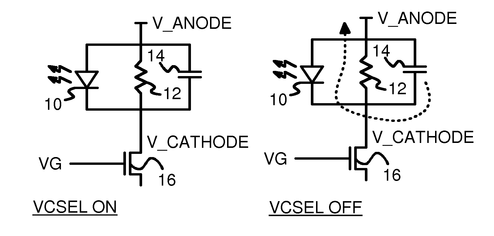
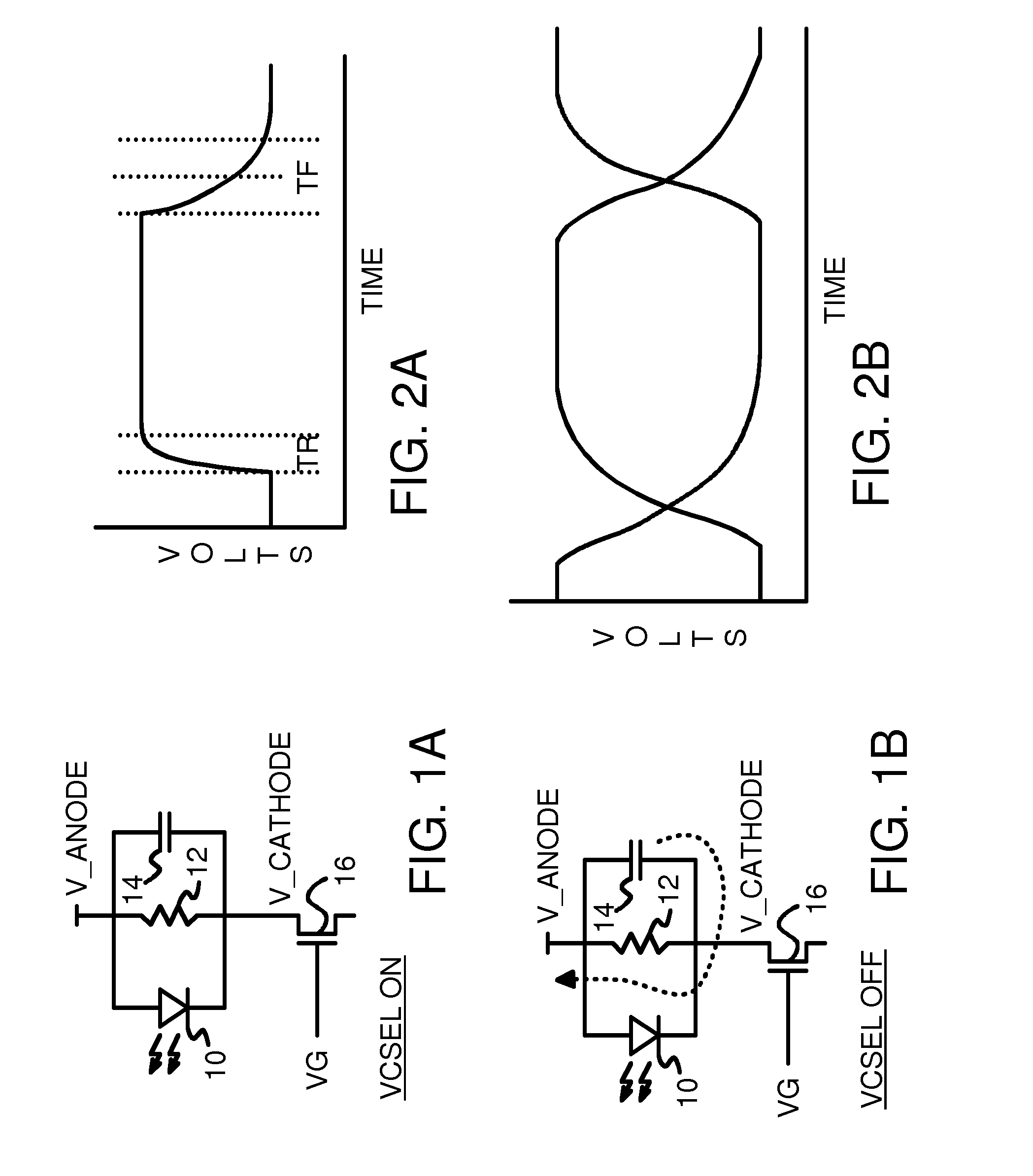
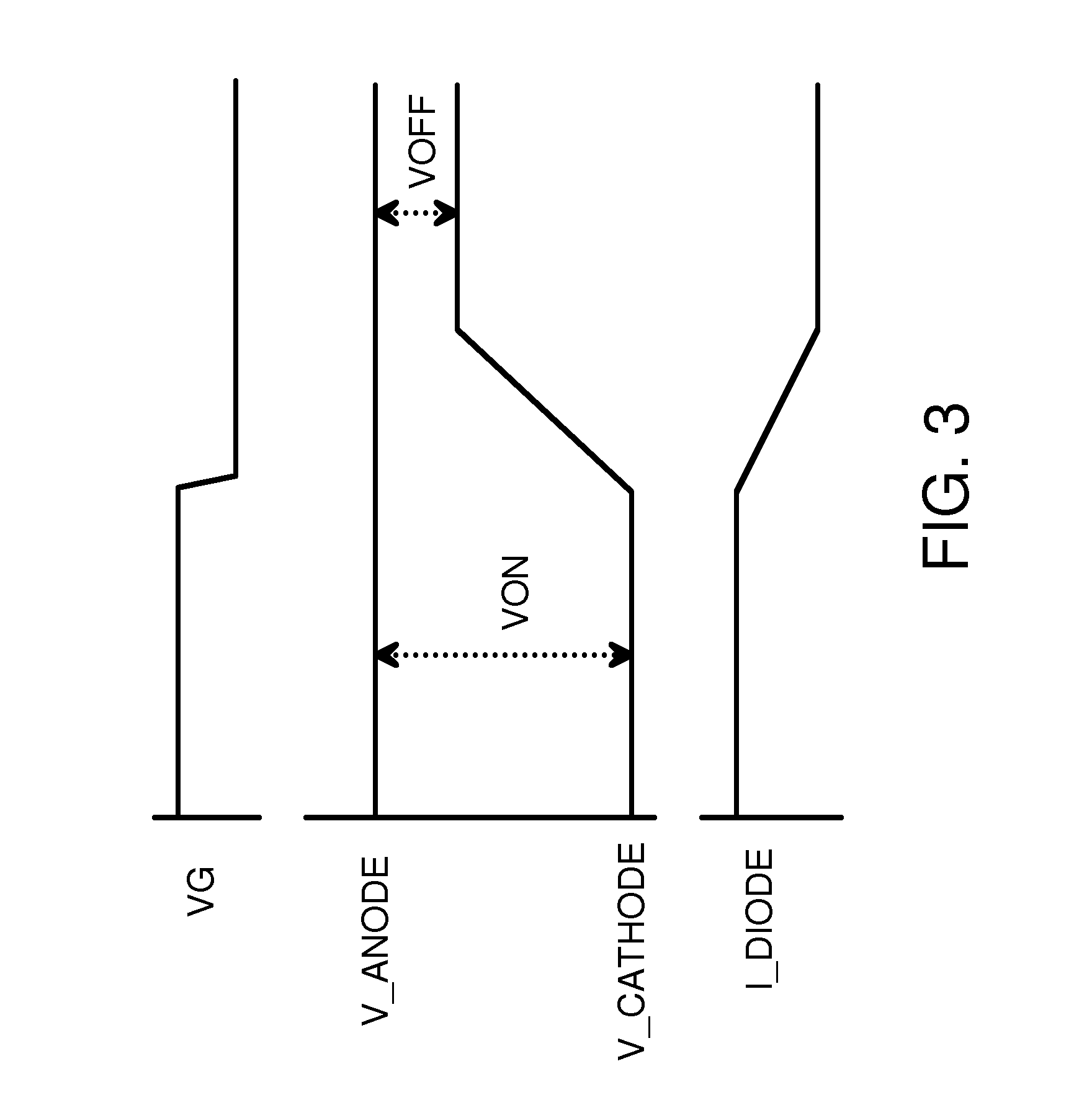
[0029]The inventor has realized that the slow physical turn-off of a VCSEL device can be compensated for by sharpening the falling edge but not sharpening the rising edge of the output of the driver circuit. An asymmetric driver circuit provides a faster fall time while maintaining a fast rise time. When combined with a physical...


PUM


Abstract

A laser driver circuit compensates for non-linear behavior of Vertical-Cavity Surface-Emitting Laser (VCSEL) devices. A VCSEL has an internal parasitic capacitance that is charged while the VCSEL is on. When the VCSEL turns off, this internal parasitic capacitor discharges, keeping the VCSEL on longer, increasing the physical turn-off or fall time. The laser driver circuit compensates for the slower fall time by modulating both anode and cathode terminals of the VCSEL as the VCSEL is turned on and off. Both plates of the internal parasitic capacitor are discharged at turn off, cutting the parasitic discharge time in half. A cathode driver transistor modulates the cathode voltage while a source-follower transistor modulates the anode voltage. A modulating current may be switched using a current mirror structure. Multiple source-follower transistors may be selectable in parallel, with switches to select the total anode current, allowing for programmable compensation of the fall time.

Description

FIELD OF THE INVENTION[0001]This invention relates to laser driver circuits, and more particularly to VCSEL drivers with asymmetrically sharpened edges.BACKGROUND OF THE INVENTION[0002]Lasers are used in a variety of applications, such as laser engraving, hair removal, cleaning, optical communications, and many industrial applications. Lasers are especially useful as transmitters for high-speed optical communication transmitters.[0003]Coherent laser light may be generated by a laser diode fabricated from semiconductor materials. Laser diodes that emit light in a direction parallel to the surface of the wafer require breaking the wafer before testing, resulting in high production and packaging costs.[0004]Surface-emitting laser diodes are preferred because they can be tested at wafer sort, before individual laser diodes are separated and packaged. Bad laser diodes are not packaged, resulting in lower costs. A widely available type of laser is known as a Vertical-Cavity Surface-Emitti...

Claims


Application Information

Patent Timeline
Patent Type & Authority Patents(United States)
IPC IPC(8): H01S3/13H01S5/042H01S5/183
CPCH01S5/042H01S5/183H01S5/0427H01S5/06213H01S5/06226
Inventor NG, KWAN TING
Owner HONG KONG APPLIED SCI & TECH RES INST
Why Eureka
Try Eureka