
System for swept source optical coherence tomography

a technology of optical coherence tomography and optical coherence tomography, which is applied in the field of optical coherence tomography and tunable lasers, can solve the problems of slow wavelength scanning limited by mechanical constraints or long cavity lifetime, incomplete wavelength coverage, and tunable lasers used in prior years, and achieve the effect of broadening the effective gain bandwidth of its active region

Active Publication Date: 2008-12-23
PRAEVIUM RES
View PDF5 Cites 71 Cited by
  • Summary
  • Abstract
  • Description
  • Claims
  • Application Information

AI Technical Summary

Benefits of technology

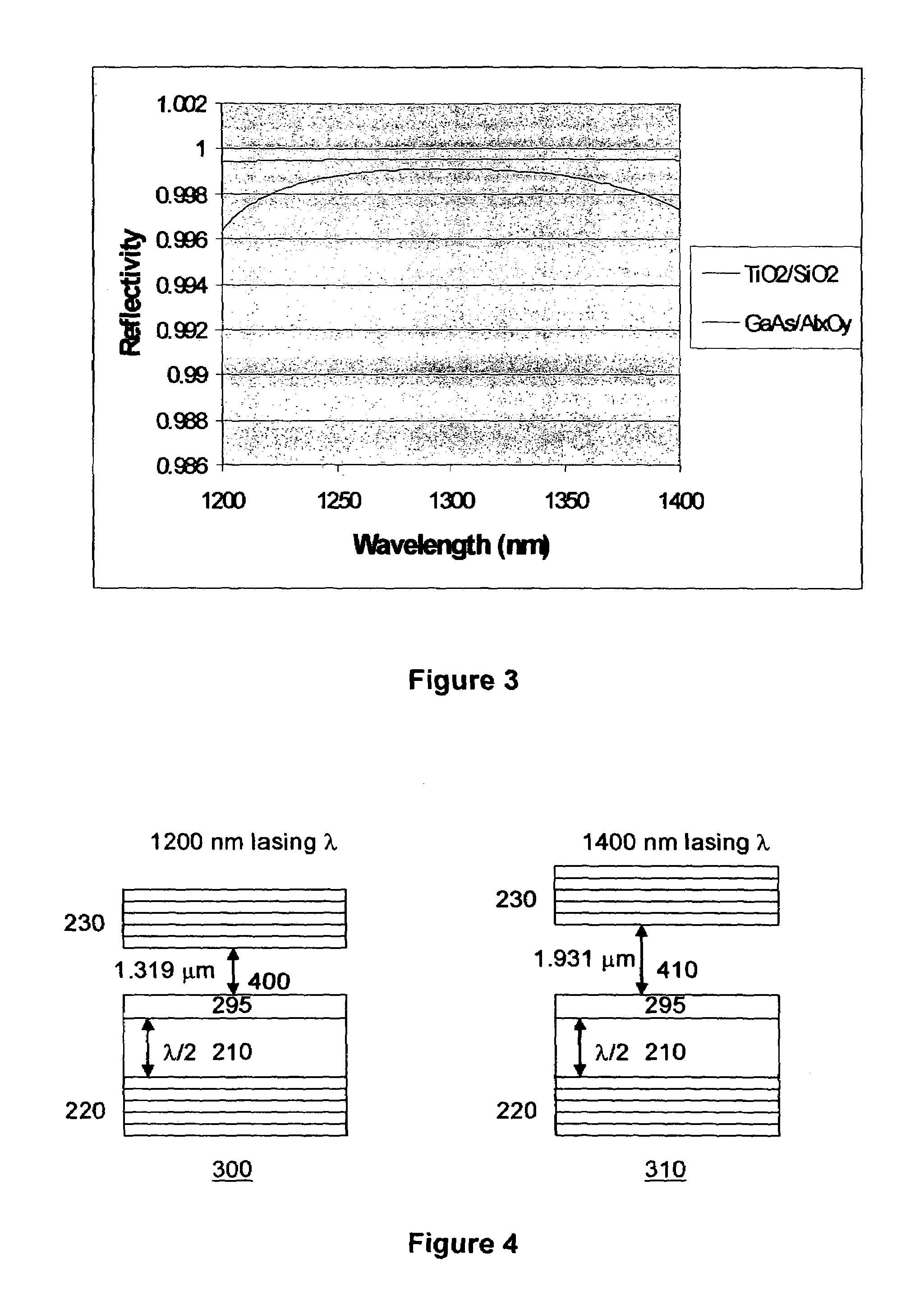
[0011]The present invention provides a swept source OCT system comprising a vertical cavity surface-emitting laser (VCSEL) with an integrated MEMs tunable mirror. The laser can have scan rates exceeding 100 kHz repetition frequency, and complete wavelength coverage over more than 100 nm. In the preferred embodiment of this system, the VCSEL has one mirror comprised of alternating layers of GaAs and Aluminum Oxide, and another mirror is comprised of an alternating dielectric stack of Titanium Dioxide (TiO2) and Silicon dioxide (SiO2) suspended on a deformable membrane. Additionally, the VCSEL is optically pumped by an edge-emitting laser, and comprises quantum wells of more than one composition or more than one quantum state to broaden the effective gain bandwidth of its active region.

Problems solved by technology

All of the tunable lasers used in prior art SSOCT systems suffer from one or more of the following problems: slow wavelength scanning limited by mechanical constraints or long cavity lifetime, incomplete wavelength coverage, or limited tuning range.
The limitation on scan rate ultimately leads to long image acquisition times, making the SS-OCT system less attractive for clinical use.
Limited tuning range translates into limited spatial resolution, and incomplete wavelength coverage translates into more shallow depth information.
The wavelength is a complex and non-monotonic function of these wavelengths, and this laser is not suitable for the kind of linear or sinusoidal wavelength sweeping required in SSOCT systems.

Method used


Image

  • System for swept source optical coherence tomography
  • System for swept source optical coherence tomography
  • System for swept source optical coherence tomography

Examples


Embodiment Construction

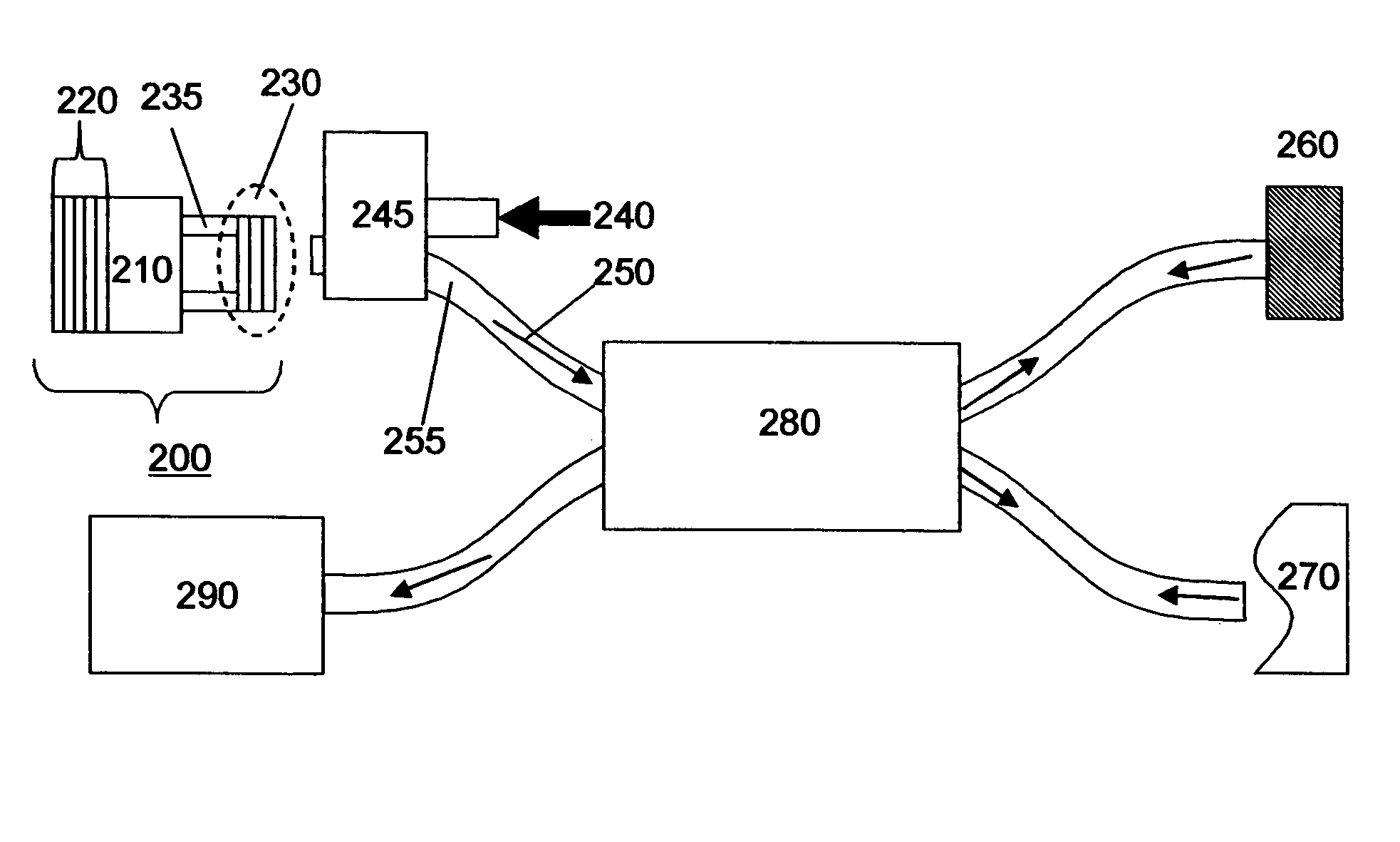
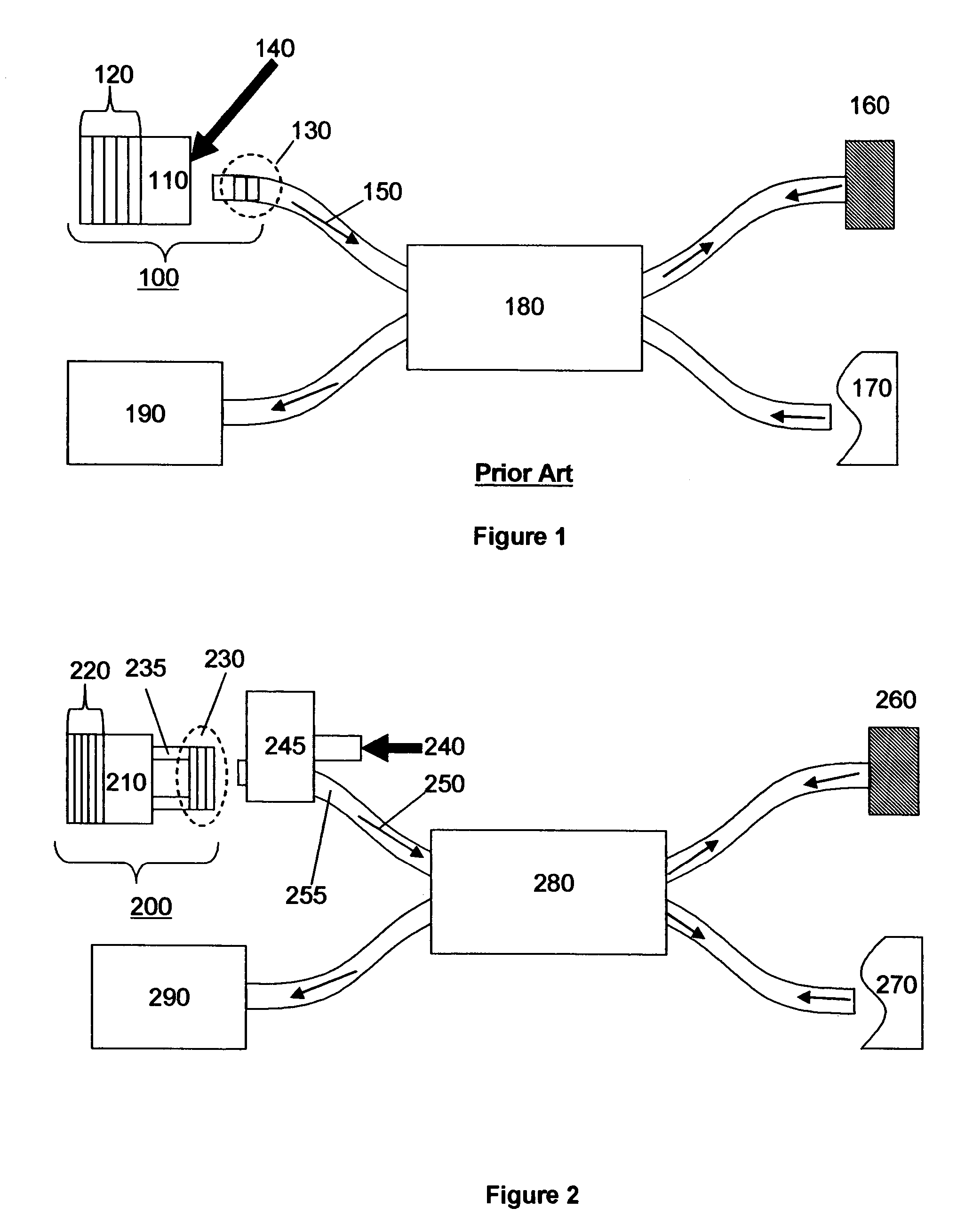
[0044]FIG. 2 shows a schematic of a preferred embodiment of the present invention. A tunable VCSEL 200 is comprised of a back mirror 220, a gain / cavity region 210, and a top mirror 230. The top mirror 230 sits on an electrostatic actuator 235, which enables electrostatic deflection of the top mirror 230. The combination of the mirror 230 and actuator 235 form an integrated tunable MEMs mirror for the VCSEL, which can be tuned by a voltage controlled deflection of the top mirror 230. A tunable emission 250 from the VCSEL 200 enters an input fiber 255, and is split to a reference mirror 260 and sample 270 by a fiber coupler 280. A pump beam 240 pumps the VCSEL 200 from the fiber 255 and through the top mirror 230. The pump 240 is coupled to the fiber 255 through a WDM coupler 245. Although having the pump enter through the top mirror 230 is preferable, alternate embodiments could employ pumping through the bottom mirror 220, or side pumping without passing through either mirror. Simil...


PUM


Abstract

A swept source Optical coherence tomography system (SSOCT) comprises a vertical cavity surface-emitting laser with an integrated MEMs tunable mirror movable by electro-static deflection. The MEMs tunable VCSEL offers scan rates greater than 100 khz and tuning ranges approaching 200 nm around 1300 nm and 150 nm around 850 nm. In the preferred embodiment of this invention, a bottom mirror of the VCSEL is comprised of a Aluminum Gallium Arsenide / Aluminum Oxide DBR stack, and a movable top mirror is comprised of a TiO2 / SiO2 DBR stack. A MEMs tunable VCSEL at 1300 nm is preferably pumped through the top mirror in a wavelength range between 1050 and 1120 nm, and a MEMs tunable VCSEL at 850 nm is preferably pumped through the top mirror in a wavelength range between 700 nm and 730 nm.

Description

CROSS-REFERENCES TO RELATED APPLICATIONS[0001]This application is entitled to the benefit of Provisional Patent Application Ser. No. 60 / 760,544, filed 2006, Jan. 20.STATEMENT REGARDING FEDERALLY SPONSORED RESEARCH OR DEVELOPMENT[0002]This invention was made under a government grant. The U.S. government may have rights in this invention.BACKGROUND[0003]1. Field of the Invention[0004]This invention relates generally to optical coherence tomography and tunable lasers.[0005]2. Description of Prior Art[0006]Optical coherence tomography (OCT) is a technique for high-resolution depth profiling of a sample below the sample surface. OCT systems include a broadband light source, means for directing radiation from that light source to a reference mirror and to a sample, and means for detecting interference of light reflected from the reference mirror with light reflected from the sample. In time-domain OCT (TDOCT), the broadband light source is typically a superluminescent diode, which simulta...

Claims


Application Information

Patent Timeline
Patent Type & Authority Patents(United States)
IPC IPC(8): H01S3/10H01S5/00
CPCA61B3/102A61B5/0059G01N21/4795A61B5/0066A61B3/10H01S5/18366A61B5/441H01S5/141G01B9/02004G01B9/02091
Inventor JAYARAMAN, VIJAYSEKHAR
Owner PRAEVIUM RES
Learn More