Sheet manufacturing apparatus
a technology of manufacturing apparatus and sheets, which is applied in the direction of papermaking machines, textiles and papermaking, paper-making machines, etc., can solve the problems of insufficient strength of manufactured sheets and incorporation of fiber aggregates, and achieve the reduction of the speed at which the defibrillator passes through the unit, the effect of reducing the occurrence of fiber aggregates and reducing the speed of defibrillator movemen
- Summary
- Abstract
- Description
- Claims
- Application Information
AI Technical Summary
Benefits of technology
Problems solved by technology
Method used
Image
Examples
first embodiment
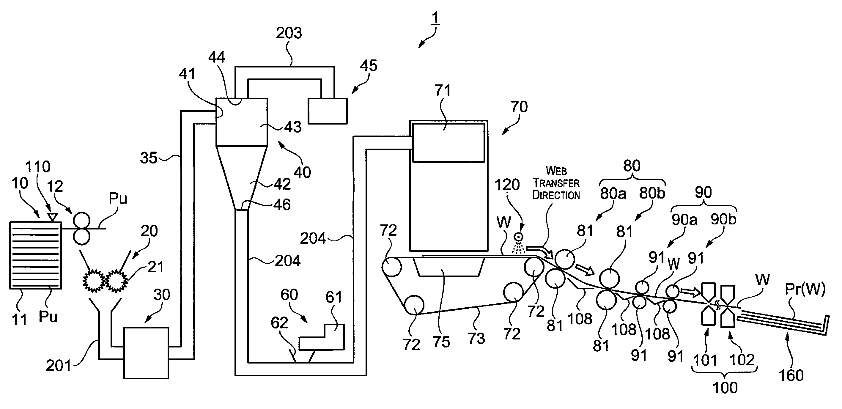
[0026]First, the configuration of a sheet manufacturing apparatus shall be described.
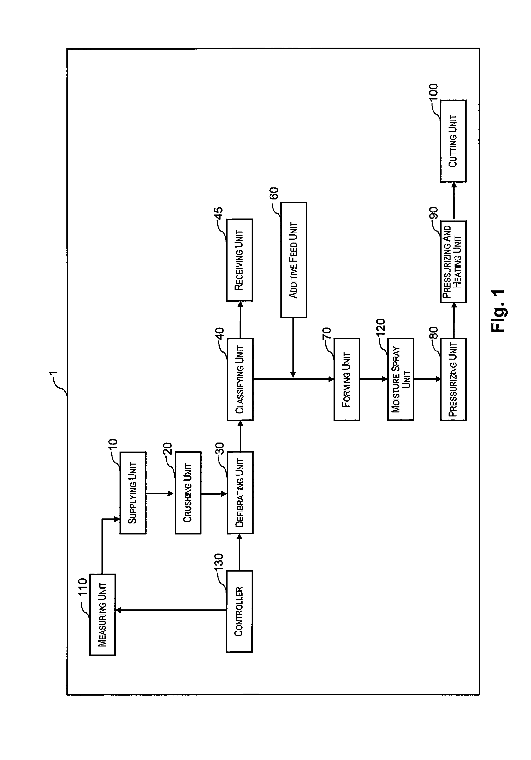
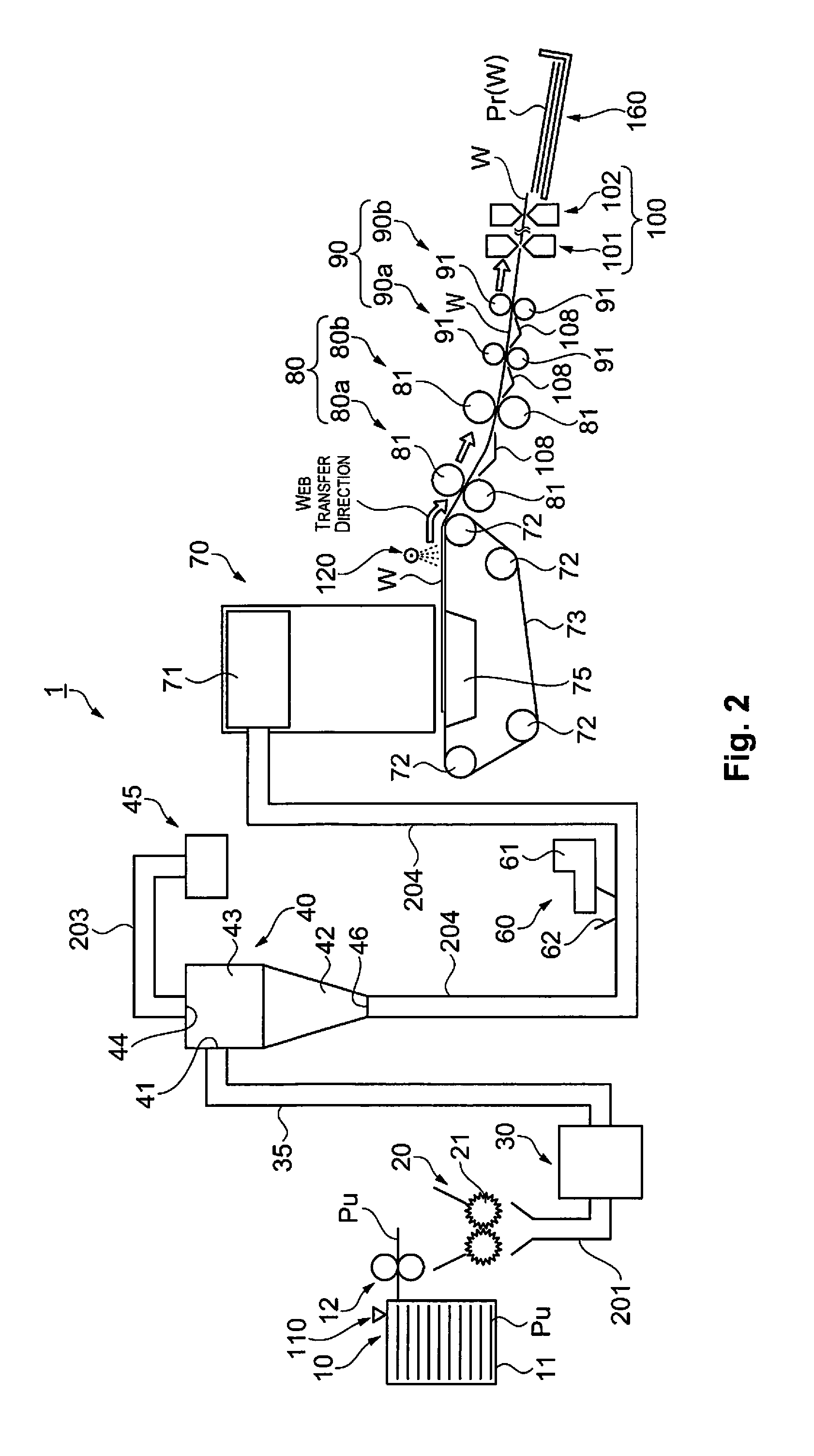
[0027]The sheet manufacturing apparatus is a device provided with a defibrating unit for defibrating a defibration object, a measuring unit for acquiring information relating to the moisture contained in the defibration object, and a controller for modifying an operating condition of the defibrating unit. Examples of stock materials serving as the defibration object supplied to the sheet manufacturing apparatus as in the present embodiment include pulp sheets or used paper PU of the A4 size that currently predominates in offices, or the like. The following provides a more detailed description.
[0028]FIGS. 1 and 2 are schematic views illustrating the configuration of a sheet manufacturing apparatus. As illustrated in FIGS. 1 and 2, a sheet manufacturing apparatus 1 is provided with a supplying unit 10, a crushing unit 20, a defibrating unit 30, a classifying unit 40, a receiving unit 45, an additive f...
second embodiment
[0060]First, the configuration of a sheet manufacturing apparatus shall be described. FIGS. 4 and 5 are schematic views illustrating the configuration of a sheet manufacturing apparatus as in the present embodiment. As illustrated in FIGS. 4 and 5, a sheet manufacturing apparatus 1a is provided with a supplying unit 10, a crushing unit 20, a defibrating unit 30, a classifying unit 40, a receiving unit 45, an additive feed unit 60, a forming unit 70, a moisture spray unit 120, a pressurizing unit 80, a pressurizing and heating unit 90, and a cutting unit 100.
[0061]The sheet manufacturing apparatus 1a is further provided with a measuring unit 110 for acquiring information relating to the moisture contained in the defibration object. A damper 230 is also provided to midway on the piping 35 by which the defibrating unit 30 and the classifying unit 40 are connected. The sheet manufacturing apparatus 1a is also provided with a controller 130 for controlling these members. The configuratio...
first example
[0072]Next, a first example shall be described. FIG. 7 is a drawing illustrating a state of defibration as in the first example. More specifically, FIG. 7 illustrates the circumstances of defibrated material (whether or not short fibers occur and whether or not fiber clumping occurs) in cases where four different kinds of changes are made to the rotational speed of the rotating blade of the defibrating unit 30, in accordance with four different kinds of water content ratio contained in the stock material being fed in. In the drawing, the symbol “◯” is indicative of the fact that neither short fibers nor fiber clumping occurred and favorable paper was obtained.
[0073]As illustrated in FIG. 7, favorable paper was obtained in cases where the water content ratio of the stock material was low and the rotational speed of the rotating blade of the defibrating unit 30 was low. In turn, defibration became excessive and short fibers occurred in cases where the water content ratio of the stock ...
PUM
| Property | Measurement | Unit |
|---|---|---|
| tensile strength | aaaaa | aaaaa |
| length | aaaaa | aaaaa |
| tensile strength | aaaaa | aaaaa |
Abstract
Description
Claims
Application Information
 - R&D
- Intellectual Property
- Life Sciences
- Materials
- Tech Scout
- Unparalleled Data Quality
- Higher Quality Content
- 60% Fewer Hallucinations
Browse by: Latest US Patents, China's latest patents, Technical Efficacy Thesaurus, Application Domain, Technology Topic, Popular Technical Reports.
© 2025 PatSnap. All rights reserved.Legal|Privacy policy|Modern Slavery Act Transparency Statement|Sitemap|About US| Contact US: help@patsnap.com


