Sheet material punching device
a technology of punching device and material, which is applied in the field of sheet material punching device, can solve the problems of failure to punch through the sheet, unfavorable events, etc., and achieve the effects of reducing the driving load, structurally simplified, and effectively preventing the increasing driving energy of the driving sour
- Summary
- Abstract
- Description
- Claims
- Application Information
AI Technical Summary
Benefits of technology
Problems solved by technology
Method used
Image
Examples
embodiment 1
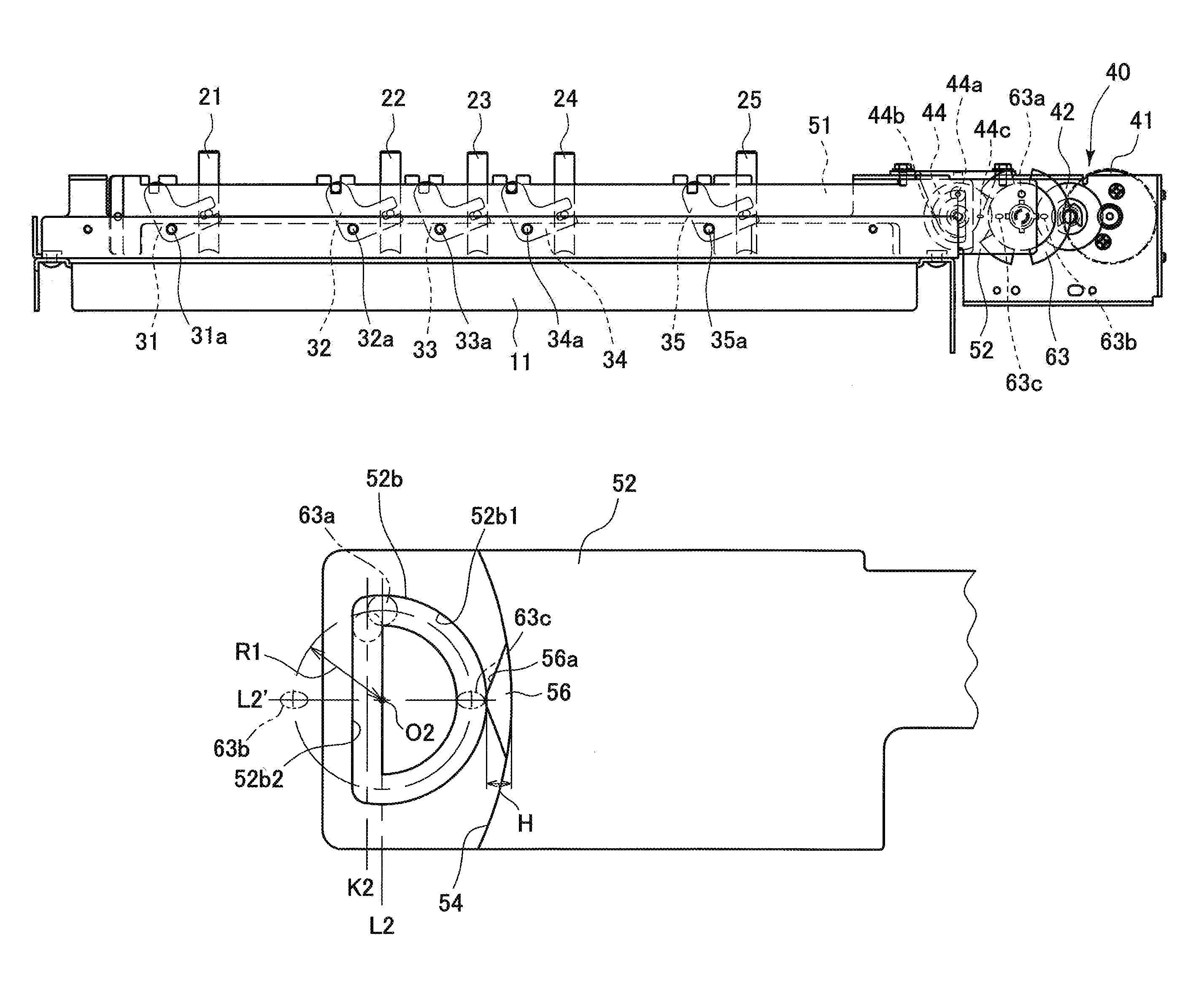
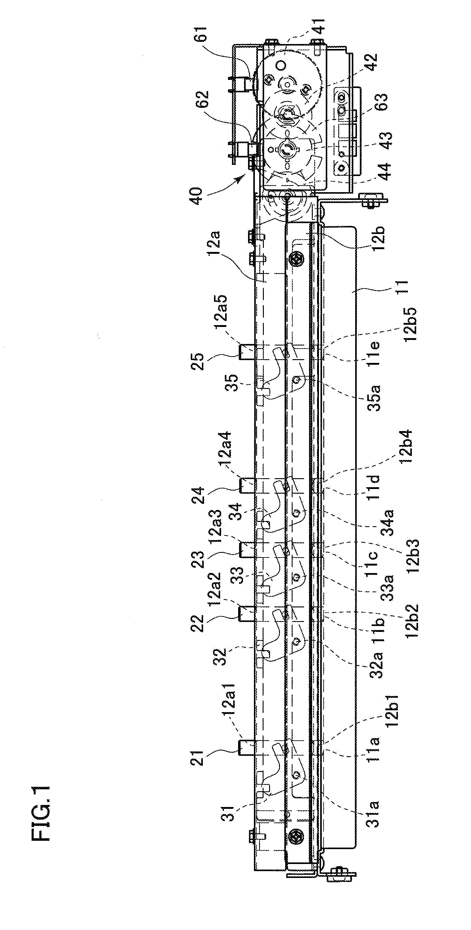
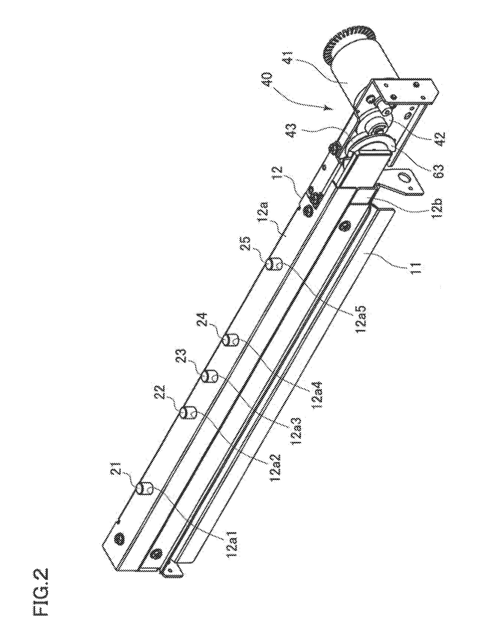
[0048]FIGS. 1 to 7 illustrate an external view of a sheet material punching device according to the invention which is used in a finisher of an image formation apparatus and structural elements of the device. The sheet material punching device includes an elongated die frame 11 formed in a U-like shape and having a plurality of die holes 11a to 11e, and an elongated frame 12 formed in a rectangular tubular shape where punches 21 to 25, links 31 to 35, a driving mechanism 40, and slide arms 51 and 52 are assembled therein. The die frame 11 and the frame 12 are secured to each other by bending the die frame 11 so as to be arranged in an opposed manner with a predefined interval therebetween, though which a sheet material is to be inserted. The interval can be formed by interposing an interval formation plate member.
[0049]The die holes 11a to 11e are formed so as to respectively correspond to the punches 21 to 25. An array of three holes spaced at a predefined pitch is formed in the sh...
second embodiment
[0103]According to the first embodiment, one cam-side engaging pin 44a (63a) is provided in the drive gear 44 (sensor filler 63). Referring to a slide arm 151 and a drive gear 144 illustrated in FIG. 16, the cam-side engaging pins 44a and 44d may be provided at positions of point symmetry (diagonal positions) with respect to an axis of rotation O1 of the drive gear 144. Any other configurations are similar to those of the first embodiment. The similar structural elements and any portions that function similar to those of the first embodiment will not be described in detail again, with the same reference symbols simply given thereto.
[0104]The cam-side engaging pins 44a and 44d and the auxiliary-cam-side engaging pins 44b and 44c are located on a circumference centering on the axis of rotation O1. Based on the clockwise direction of the axis of rotation O1 in front view of the inner-side surface of the drive gear 44 (see FIG. 11), the auxiliary-cam-side engaging pin 44b is located at ...
PUM
| Property | Measurement | Unit |
|---|---|---|
| central angle | aaaaa | aaaaa |
| central angle | aaaaa | aaaaa |
| angle | aaaaa | aaaaa |
Abstract
Description
Claims
Application Information
 - Generate Ideas
- Intellectual Property
- Life Sciences
- Materials
- Tech Scout
- Unparalleled Data Quality
- Higher Quality Content
- 60% Fewer Hallucinations
Browse by: Latest US Patents, China's latest patents, Technical Efficacy Thesaurus, Application Domain, Technology Topic, Popular Technical Reports.
© 2025 PatSnap. All rights reserved.Legal|Privacy policy|Modern Slavery Act Transparency Statement|Sitemap|About US| Contact US: help@patsnap.com


