Universal punching bag support apparatus

a support apparatus and universal technology, applied in the field of universal support apparatus for punching bags, can solve the problems of hindering the user from striking the bag, heavy bag or focus bag, and the accompanying means of support require substantial rigidity and stability, and achieve the effect of sufficient stability for repetitive striking

Active Publication Date: 2015-04-21
SAGALL JASON
View PDF7 Cites 2 Cited by
  • Summary
  • Abstract
  • Description
  • Claims
  • Application Information

AI Technical Summary

Benefits of technology

[0016]These teachings provide apparatus, systems and methods for which a punching bag, or a punching bag and a rebound platform, can be mounted and secured to a plurality of architectural openings, including various architraves, e.g., a doorframe, such that the mounting utilizes surrounding architectural structures and surfaces without modification, alteration, or injury to those structures and surfaces, and such that the apparatus as mounted provides sufficient stability for repetitive striking of a punching bag.
[0019]The bag-support member could be adjustably coupled to an upper clamp assembly attached to an upper portion of the doorframe such that, as mounted, the support apparatus is proximate to the doorframe at a plurality of heights and depths to facilitate the use of a plurality of punching bags. The upper clamp assembly could assist in generally securing the apparatus in its mounted position and reducing movement of the apparatus during punching bag use. The upper clamp assembly could include one or more clamps comprised of at least one front member, at least one rear member, and at least one tightening mechanism, such that each clamp in the assembly could be tensioned around a front side and a rear side of the doorframe. Such clamping means could prevent the apparatus from being jarred from its mounted position and falling as a result of lateral movement of the punching bag or, in particular, by upward movement of a speed bag rebounding against an attached platform.
[0024]Similarly, one or more of the bag-support members could comprise a series of coupling points arranged horizontally such that the coupling between the bag-support member and the upper clamp assembly could also be horizontally adjustable—for example: in at least one-half-inch or one-inch increments, or infinite sliding adjustability, within a span of at least three inches. Such horizontal variability could allow the bag-support member, and thus the punching bag itself, to be positioned forward or backward, relative to the depth of the doorway, to suit the preference of the user. Further, in an embodiment comprising a bag-support member configured as an elongated horizontal member that abuts the front-left side and the front-right side of the doorframe, such horizontal adjustment in the coupling of the bag-support member to the upper clamp assembly could facilitate the mounting of the apparatus with an attached rebound platform in doorways with a plurality of frame dimensions—for example, 5 inches deep, 6½ inches deep, or 7 inches deep, such that the platform rests in a perfectly level position.
[0025]In some embodiments, the coupling between the horizontal and vertical elements of the bag-support members is envisioned to be rotatable in order to compact the apparatus when unmounted, to allow more convenient storage or ease in transport, for example.
[0027]It is envisioned that any of the clamp assemblies could comprise at least one or two support materials: a first material that is at least semi-rigid, to provide the primary structure of the clamp; and a second material that comprises a padding, to provide protection to the surfaces of the doorframe, wall or other architectural structures with which the clamp comes into contact. Moreover, a plurality of padding materials could be employed on the clamps or any part of the support apparatus to provide grip, or to protect against scratches or blemishes on the architectural surfaces, or to dampen vibration of the apparatus during punching bag use, or to absorb shock to the apparatus or the architectural structures during punching bag use. Alternatively, the first material could comprise a semi-rigid material that also functions as a padding material, such as a hard rubber. Such a material could be the only material of which the clamps are comprised. Contemplated semi-rigid or rigid materials include, but are not limited to, steel, aluminum, hardwood, fiberglass, hard plastic, and hard rubber. Contemplated padding materials include, but are not limited to, soft rubber, foam rubber, soft plastic, vinyl, felt, and cloth.

Problems solved by technology

Since this type of use requires minimal loss of energy in the struck bag, the platform and the accompanying means of support require substantial rigidity and stability.
A platform or support apparatus that is generally unstable or that significantly vibrates will deaden the rebound of the bag and thus hinder the user from striking the bag with the speed and rhythm that is paramount to speed bag users.
Previous references that could provide support for a type of punching bag other than a speed bag and rebound platform—for example, a heavy bag or focus bag—fail at least to also provide adequate support for a speed bag and rebound platform.
Previous references that could provide support for a speed bag and rebound platform fail at least to employ a means or apparatus that would also provide adequate support for other types of punching bags.
Further, previous references that could provide support for a speed bag and rebound platform fail at least to provide such support in one or more of the following ways:1) The reference fails to employ a method or apparatus that would not effectively alter or modify the supporting structures (for example, a wall or ceiling), in that it utilizes screws, bolts, anchors, nails, adhesives, or other fastening methods that would penetrate the supporting structures in order to achieve a requisite level of support;2) The reference fails to employ a method or apparatus that would not cause markings or indentations to the supporting structures, in that the apparatus invariably presses into the supporting structures in order to achieve a requisite level of support or as a result of movement during punching bag use;3) The reference fails to employ a method or apparatus that would not be a safety hazard, in that its mounting or tensioning means do not ensure against the slipping or falling of the apparatus as a result of movement during punching bag use or merely under the force of gravity;4) The reference fails to employ a method or apparatus that would achieve a level of stability and performance required for speed bag use as described above, in that it does not provide for the use of a solid rebound platform or does not provide requisite high-rebound and low-vibration characteristics.

Method used


Image

  • Universal punching bag support apparatus
  • Universal punching bag support apparatus
  • Universal punching bag support apparatus

Examples


Embodiment Construction

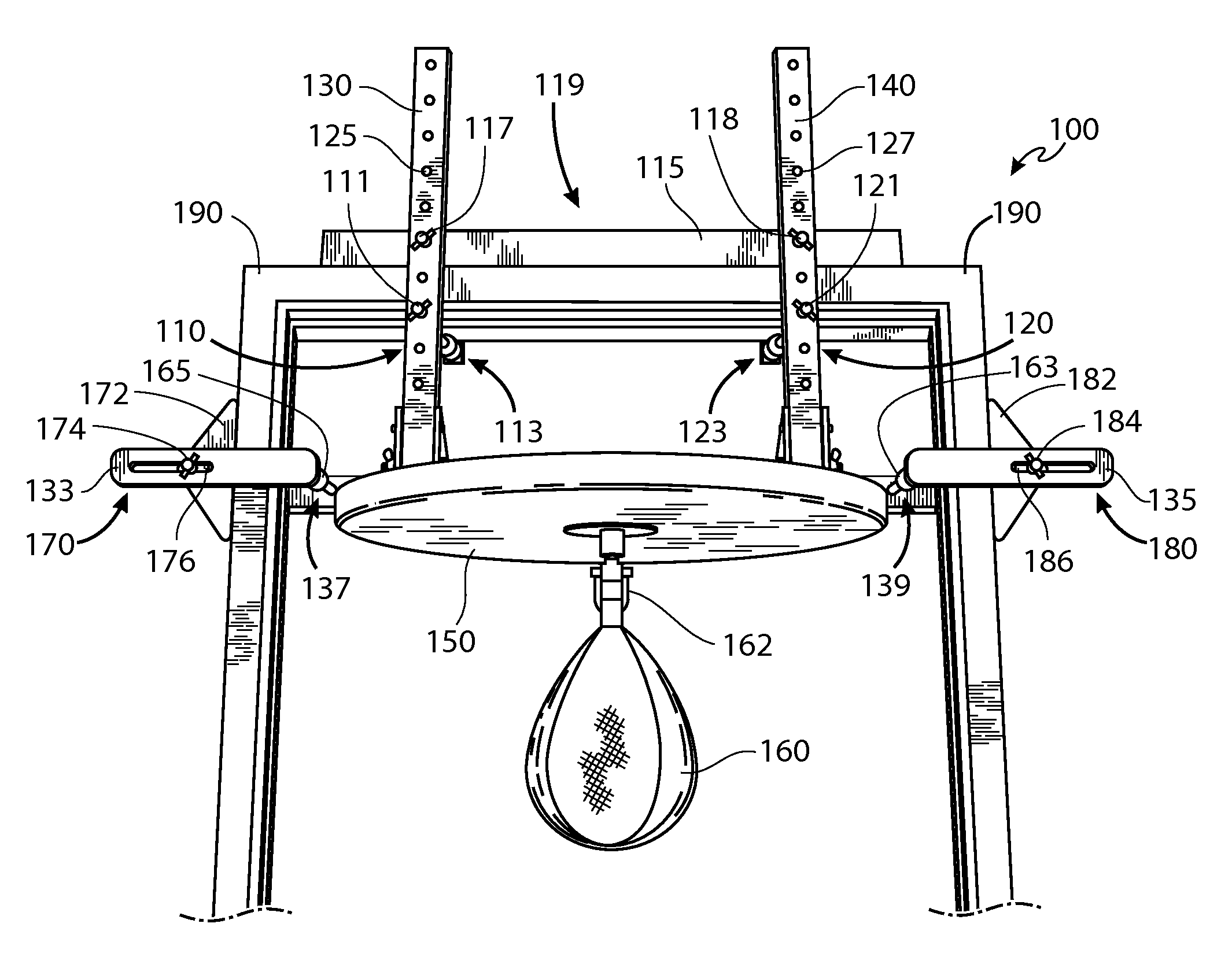
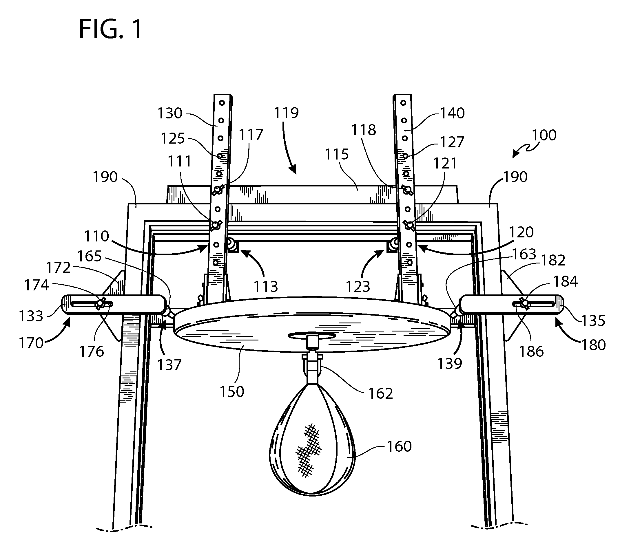
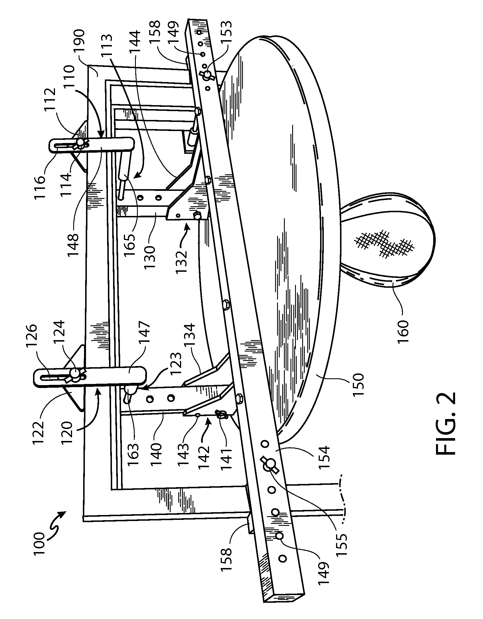
[0043]Previous support methods that rely on clamping suffer from the dilemma that, in order to achieve optimal support and stability by clamps alone, a support apparatus would have to be lighter than a weight that would maximize performance use. Previous methods that rely on leveraging suffer from the dilemma that, in order to achieve optimal support and stability by leverage points alone, the support apparatus would have to be heavier than a weight that would be necessary for high-performance use, and this could make installation more difficult or impossible in some situations. Therefore, by either method, apparatus usability and performance must be compromised for the sake of clamping or leveraging effectiveness.

[0044]The disclosed methods provide several advantageous technical effects over previous methods. The methods herein teach a clamping and leveraging support means together, such that the two work integrally and optimally in a plurality of embodiments. No longer must the ap...


PUM


Abstract

This disclosure describes an apparatus and methods to support a punching bag, or a punching bag and rebound platform, within a doorway or other architectural opening. Mounting the apparatus does not involve modifying or altering the supporting architectural structures and surfaces (e.g., with screws, brackets, adhesives, etc.). Clamps are instrumental in safely securing the apparatus and stabilizing it for high-performance use of a plurality of punching bags. Adjustment mechanisms not only facilitate the mounting of the apparatus to a plurality of doorframes and other architraves but also accommodate the height and depth preferences of a user. In addition, a folding mechanism allows the apparatus to be compacted for storage or transport.

Description

BACKGROUND OF THE INVENTION[0001]It is known to support a punching bag by attaching it to a stable structure for appropriate use. Previous references include those that teach a punching bag support method involving, for example, an exercise machine, telescoping poles, a freestanding apparatus, or various apparatuses that mount to a ceiling or overhead architectural structure, a wall, a door, a doorframe, a ceiling and a floor, or a ceiling and a wall.[0002]As used herein, a “punching bag support apparatus,” or “support apparatus,” is an apparatus made to support a plurality of types of punching bags, including weighted or inflated bags—for example: a heavy bag, angle bag, focus bag, or speed bag. In the example of a speed bag, the support apparatus is made to also support a horizontal rebound drum, more commonly known, and referred to herein, as a rebound platform or simply a platform.[0003]In fact, a speed bag requires special considerations to support the bag for proper use. A spe...

Claims


Application Information

Patent Timeline
Patent Type & Authority Patents(United States)
IPC IPC(8): A63B21/00A63B21/16A63B69/20A63B71/02
CPCA63B69/201A63B69/205A63B71/023A63B21/1627A63B21/1636A63B2210/50A63B2225/09Y10S482/904A63B69/305A63B69/222
Inventor SAGALL, JASON
Owner SAGALL JASON
Why Eureka
Try Eureka