Antenna feeding structure and antenna
a technology of antenna and feeding structure, applied in the field of antennas, can solve the problems of increasing manufacturing cost, increasing complexity and difficulty of antenna design, and not proposing an efficient feeding structure for improving the performance of antennas, etc., and achieves the effect of simple structure and broadband characteristics
- Summary
- Abstract
- Description
- Claims
- Application Information
AI Technical Summary
Benefits of technology
Problems solved by technology
Method used
Image

Examples
first embodiment
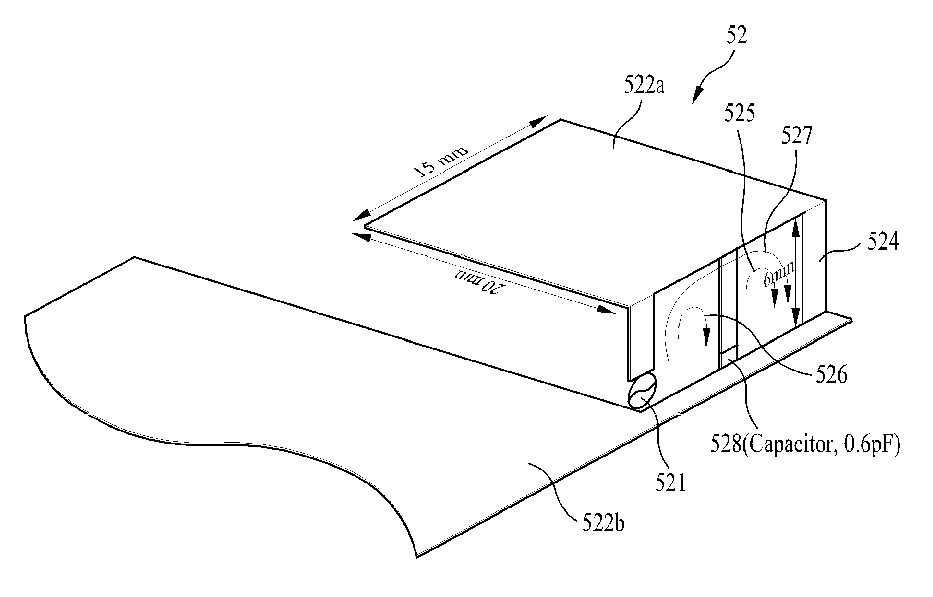
[0056]FIG. 5(b) is a view showing an antenna applying a feeding structure according to the present invention. The antenna shown in FIG. 5(b) is an example of an antenna applying the feeding structure shown in FIG. 4(a).
[0057]The antenna according to the embodiment includes a feeding unit 521, a radiator 522a, a ground plane 522b for providing a ground potential and operating as a radiator, a first loop 526 containing a feeding unit 521 and a capacitive element 528, a second loop 525 containing the capacitive element 528 and a conducting line 524, and a third loop 527 containing the feeding unit 521 and the conducting line 524.
[0058]At this point, since each of the loops 526, 525 and 527 is a structure for feeding RF signals to the radiators 522a and 522b, it can be referred to as a feeding structure.
[0059]A resonance frequency of an antenna having a feeding structure according to the present invention can be controlled in a method described below.
[0060]First, if inductance of the se...
second embodiment
[0065]FIG. 7 is a view showing an antenna applying a feeding structure according to the present invention.
[0066]The antenna 70 according to the embodiment includes a ground 71 and a capacitor 72 operating as a radiator, a clearance 73 which is an area where the ground 71 is removed, and a feeding structure 700 formed inside the clearance 73.
[0067]Meanwhile, the feeding structure 700 includes a first loop 710, a second loop 730, and a third loop 720. The first loop 710 contains a feeding unit 75 and a capacitive element 74. Meanwhile, the second loop 730 contains the capacitive element and the ground 71 functioning as a conducting line. In addition, the third loop 720 contains the feeding unit 75 and the ground 71 functions as a conducting line.
[0068]The feeding structure 700 according to the embodiment also includes a third loop 720 corresponding to a low frequency loop, a second loop 730 corresponding to an intermediate frequency loop, and a first loop 710 corresponding to a high f...
third embodiment
[0069]FIG. 8 is a view showing an antenna applying a feeding structure according to the present invention.
[0070]The antenna 80 according to the embodiment shows a case where radiators 82a and 82b are spaced apart from a feeding structure 800. That is, although the radiators 82a and 82b are spaced apart from the feeding structure 800, the radiators 82a and 82b (or a radiator loop 84 connected to the radiators 82a and 82b) and the feeding structure 800 are coupled by magnetic flux generated by the feeding structure 800. Accordingly, the feeding structure 800 may feed RF signals to the radiators 82a and 82b in an electromagnetic method.
[0071]The feeding structure 800 of the antenna 80 according to the embodiment includes a first loop 810 containing a feeding unit 81 and a capacitive element 83, a second loop 820 containing the capacitive element 83 and a conducting line, and a third loop 830 containing the feeding unit 81 and the conducting line.
[0072]The feeding structure 800 accordin...
PUM
 Abstract
Description
Claims
Application Information
 - R&D
- Intellectual Property
- Life Sciences
- Materials
- Tech Scout
- Unparalleled Data Quality
- Higher Quality Content
- 60% Fewer Hallucinations
Browse by: Latest US Patents, China's latest patents, Technical Efficacy Thesaurus, Application Domain, Technology Topic, Popular Technical Reports.
© 2025 PatSnap. All rights reserved.Legal|Privacy policy|Modern Slavery Act Transparency Statement|Sitemap|About US| Contact US: help@patsnap.com