Method for evaluation of density profile in carbon/carbon material and method for production of standard density test block used therein

a density profile and carbon/carbon material technology, applied in the direction of manufacturing tools, instruments, specific gravity measurement, etc., can solve the problems of inconvenient use, inconvenient measurement of density profile, inability to meet the requirements of density measurement, etc., and achieve the effect of eliminating air spaces between

Inactive Publication Date: 2015-03-24
AGENCY FOR DEFENSE DEV
View PDF15 Cites 7 Cited by
  • Summary
  • Abstract
  • Description
  • Claims
  • Application Information

AI Technical Summary

Benefits of technology

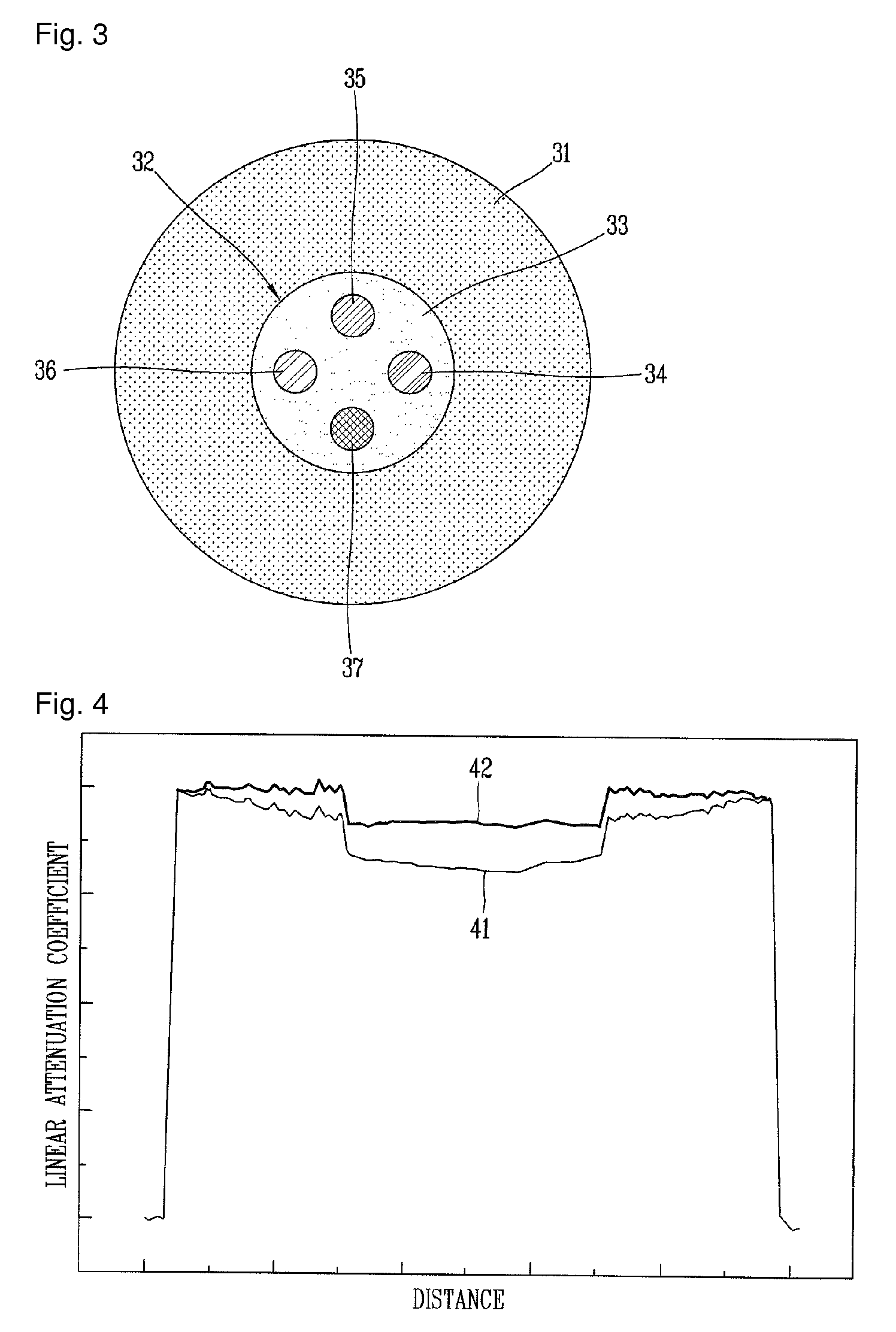
[0014]To achieve the object or other advantage of the present invention, there is provided a method for evaluating a density profile in a carbon / carbon material, in a method for quantitatively measuring a density profile in a carbon / carbon material, the method including, a first step of preparing a standard density test block to be inserted in the carbon / carbon material, wherein the standard density test block is produced by using the same type of material as the carbon / carbon material and thereafter inserted in the carbon / carbon material, a second step of radiating X-rays onto the carbon / carbon material having the standard density test block inserted so as to obtain and correct computed tomographic image, and a third step of measuring a physical density by use of a linear attenuation coefficient of the computed tomographic image. The standard density material and the beam hardening correction material are made of a carbon-based material, the carbon-based material may include graphite.
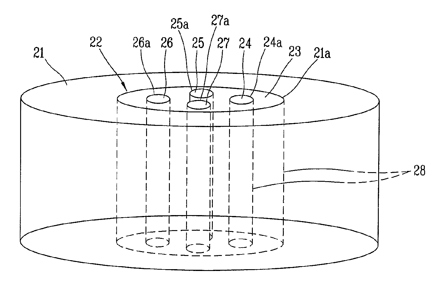
[0015]The standard density test block may include a plurality of standard density materials each having a different density, and a beam hardening correction material having a plurality of internal holes, the plurality of standard density materials being inserted into the corresponding internal holes in a spaced state therebetween.
[0016]At least two of the plurality of standard density materials may be produced to constantly have a minimum density difference for allowing check of resolution.
[0017]Vacuum grease may be coated between the internal holes of the beam hardening correction material and the standard density materials for eliminating air spaces therebetween.
[0018]An outer appearance of the beam hardening correction material may be produced in a shape capable of being inserted in the carbon / carbon material, and vacuum grease may be coated between an outer surface of the correction material and inner wall surfaces of the holes of the carbon / carbon material for eliminating air spaces therebetween.
[0019]The second step may be configured to radiate the X-rays to the carbon / carbon material having the standard density test block inserted therein, to simultaneously measure the standard density test block and the carbon / carbon material.

Problems solved by technology

The combustion test results show an inconsistent erosion rate in spite of using carbon / carbon materials having similar densities with respect to an entire volume, which is caused directly due to the local density difference of the carbon / carbon materials.
The local density of the carbon / carbon material can be physically computed by cutting, dissection and the like, but such mechanisms come with destruction of the carbon / carbon material.
Furthermore, if densities of those physically destructed carbon / carbon materials are computed, excessive time and cost are required.
However, even if adapting one of such techniques, it is difficult to quantitatively measure a physical density.
Nevertheless, density measurement still relies on experiences of engineers and causes large deviation between engineers, and different results are derived by the same engineer.
However, this method has a disadvantage of low reproducibility and accuracy.
There are many methods proposed for measuring bone mineral density using X-ray images, but the difference of X-ray attenuation cannot be obviously specified with only one X-ray image, thereby generating considerable measurement errors.
However, the density difference has merely been discriminated by measuring linear attenuation coefficients of bones, fat, muscles and the like and no quantitative density value has been given.
Also, the use of 511-KeV annihilation radiation has limitation to a transmission capability through an object and the use of radioactive isotope is always linked to the problem of the radioactive safety supervision.
Such use of the standard test block can be useful for fabrication of orthopedic prostheses with a specific bone structure and correction of the bone structure; however, no quantitative density value has been provided.
The existing tomography technique could not measure the accurate width and density with respect to a structure having a width below a minimum resolution value of image; however, this technique has measured the width of a specific structure, the width smaller than the minimum resolution value, by measuring a full width at half maximum (FWHM) based upon a maximum density value.
However, this technique has a disadvantage that the local density cannot directly be measured because the correlation between the density and the linear attenuation coefficient of different types of materials, such as distilled water, NaCl water solution, magnesium and PVDF, which are inserted in inner holes made of acryl, is different from the correlation between the density and the linear attenuation coefficient of a carbon group.
Thus, this technique must perform complicated processes of correcting each slice image to evaluate the local density.
In addition, the standard density test block produced in the technique uses the acryl-based material other than the carbon / carbon material, which disables a direct correction of beam hardening, resulting in a disadvantage of correcting and checking the beam hardening by using the cylindrical carbon / carbon material.

Method used


Image

  • Method for evaluation of density profile in carbon/carbon material and method for production of standard density test block used therein
  • Method for evaluation of density profile in carbon/carbon material and method for production of standard density test block used therein
  • Method for evaluation of density profile in carbon/carbon material and method for production of standard density test block used therein

Examples


Embodiment Construction

[0033]Hereinafter, description will be given of a method for measuring the density profile of a carbon / carbon material in accordance with the preferred embodiment of the present invention, with reference to the accompanying drawings.

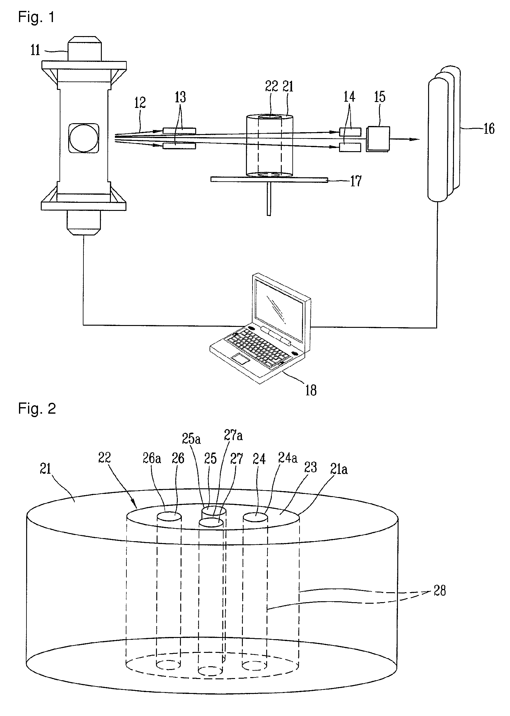
[0034]FIG. 1 is a schematic construction view of a density profile measurement system of a carbon / carbon material in accordance with the present invention.

[0035]The density measurement system of the carbon / carbon material according to the present invention may include an X-ray radiation source 11 for generating X-rays, X-rays 12, a fan beam collimator 13, a slice thickness control lead shield 14, a dose control lead shield 15, an X-ray detector 16, a rotatable working table 17 and a controller or image processor 18.

[0036]The fan beam collimator 13 may be disposed in front of the X-ray radiation source 11. X-rays 12 generated by the X-ray radiation source 11 pass through the fan beam collimator 13, thereby minimizing the scattered X-rays and obtaining onl...


PUM

PropertyMeasurementUnit
densityaaaaaaaaaa
densityaaaaaaaaaa
density testaaaaaaaaaa

Abstract

Disclosed are a method for evaluating a local density profile in a carbon / carbon material and a method for producing a standard density test block capable of quantitatively evaluating the density profile in the carbon / carbon material, wherein the method for evaluating the density profile includes a first step of preparing a standard density test block to be inserted in the carbon / carbon material, wherein the standard density test block is produced by using the same type of material as the carbon / carbon material and thereafter inserted in the carbon / carbon material, a second step of radiating X-rays onto the carbon / carbon material having the standard density test block inserted so as to obtain and correct computed tomographic image, and a third step of measuring a physical density by use of a linear attenuation coefficient of the computed tomographic image, whereby the local density profile can accurately be evaluated by use of a nondestructive testing and additionally such method can be utilized as an excellent means for improving processes and ensuring quality.

Description

TECHNICAL FIELD[0001]The present invention relates to a method for producing a standard density test block capable of quantitatively evaluating the density profile of a carbon / carbon material by employing a nondestructive testing, and a method for computing physical density through a computed tomography.BACKGROUND ART[0002]Carbon / carbon material denotes a porous material having only carbon left therein due to cycles of carbonization and impregnation. The porous portions locally have a density difference. The combustion test results show an inconsistent erosion rate in spite of using carbon / carbon materials having similar densities with respect to an entire volume, which is caused directly due to the local density difference of the carbon / carbon materials.[0003]The local density of the carbon / carbon material can be physically computed by cutting, dissection and the like, but such mechanisms come with destruction of the carbon / carbon material. Consequently, supplementary data is merel...

Claims


Application Information

Patent Timeline
Patent Type & Authority Patents(United States)
IPC IPC(8): G01N23/06G01N9/24G01N23/083G01N1/28G01N23/04
CPCG01N23/046G01N9/24G01N2223/3306G01N2223/633G01N2223/419G01N2001/2893Y10T29/4998
Inventor KIM, DONG RYUNYUN, NAM GYUN
Owner AGENCY FOR DEFENSE DEV
Why Eureka
Try Eureka