Electric power steering apparatus
a technology of electric power steering and steering shaft, which is applied in the direction of steering initiation, instruments, vessel construction, etc., can solve the problems of inability to prevent self-steering or control error output with certainty, and achieve the effect of accurate torque detection valu
- Summary
- Abstract
- Description
- Claims
- Application Information
AI Technical Summary
Benefits of technology
Problems solved by technology
Method used
Image
Examples
first embodiment
[0225]An explanation will next be made to an operation of the
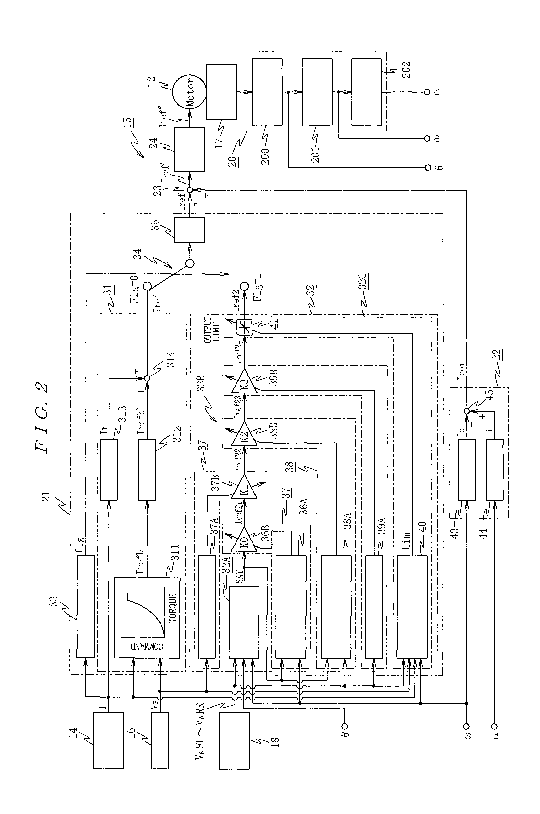
[0226]Now, let us suppose that the steering torque sensor 14 is in the normal state. The steering torque T detected by the steering torque sensor 14 in the torque sensor error detecting part 33 provided in the steering assist command calculating part 21 does not satisfy the torque sensor error condition. For this reason, the torques sensor error detecting flag Flg is set to “0”, and the torques sensor error detecting flag Flg is output to the command selecting part 34.
[0227]On that account, the command selecting part 34 selects the first steering assist torque command calculating part 31 and variations of the first steering assist torque command Iref1 output from the front steering torque command calculating part 31 is limited by the rate limiter 35, and it is output as a steering assist command Iref to the adder 23.
[0228]At this moment, it is assumed that a vehicle is stopped with the steering wheel 1 as a neutral positio...
second embodiment
[0312]An explanation will next be made to the present invention deferring to FIG. 22 to FIG. 24.
[0313]In the second embodiment, a motor angle θ detected by the motor angle signal sensor 200 is also supplied to the wheel rotation speed limiting value calculating part 40b in the control output limiting value calculating part 40 of the torque limiting part 32C, and the wheel rotation speed limiting value is calculated using the motor angle θ .
[0314]That is, in the second embodiment, as shown in FIG. 22, the motor angle θ is input to the control output limiting value calculating part 40, and as show in FIG. 23, the motor angle θ is input to the wheel rotation speed limiting value calculating part 40b.
[0315]In the wheel rotation speed limiting value calculating part 40b, as with the aforementioned first embodiment, the wheel rotation speed limiting value calculating processing shown in FIG. 16 is executed based on the motor angular velocity ω, and the wheel rotation speed limiting value...
third embodiment
[0328]An explanation will then be made to the present invention referring to FIG. 26.
[0329]In the third embodiment, the embodiment aims at improving estimation accuracy of the self-aligning torque estimation value SAT based on the four-wheel rotation speed and the motor angle.
[0330]Namely, in the third embodiment, although the third embodiment has the same system configuration as the second embodiment, a self-aligning torque estimation selecting processing will be executed, by the self-aligning torque estimating part 32A shown in FIG. 26.
[0331]The self-aligning torque estimation value selecting processing is executed as a timer interrupt process invoked for every preset time (e.g. 10 msec). First, at step S81, the self-aligning estimation value SAT (n) output from the phase correction part 331 and the motor angle (θ) detected by the motor angle signal sensor 200. Then, the processing proceeds to step S82.
[0332]At step S82, the determination is made on whether or not the self-alignin...
PUM
 Abstract
Description
Claims
Application Information
 - R&D
- Intellectual Property
- Life Sciences
- Materials
- Tech Scout
- Unparalleled Data Quality
- Higher Quality Content
- 60% Fewer Hallucinations
Browse by: Latest US Patents, China's latest patents, Technical Efficacy Thesaurus, Application Domain, Technology Topic, Popular Technical Reports.
© 2025 PatSnap. All rights reserved.Legal|Privacy policy|Modern Slavery Act Transparency Statement|Sitemap|About US| Contact US: help@patsnap.com


