System for wave energy harvesting employing transport of stored energy

a technology of energy storage and wave energy, applied in the energy field, can solve the problems of increasing the cost of cable maintenance, so as to reduce the usefulness of these technologies

Active Publication Date: 2015-03-03
FRAUNHOFER USA
View PDF5 Cites 2 Cited by
  • Summary
  • Abstract
  • Description
  • Claims
  • Application Information

AI Technical Summary

Benefits of technology

[0006]Other drawbacks of existing approaches include the dependence on specific sites. Many technologies can only work in certain unusual locations, such as where the amplitude of the tide is very large, or where ocean currents are very strong. These limitations reduce the usefulness of these technologies. Permanently installed equipment also suffers the wearing effects of the harsh marine environment and sun exposure, and can create environmental and esthetic degra...

Problems solved by technology

Existing approaches for harvesting energy from waves, tides, and ocean currents, as well as offshore wind, suffer from at least three significant weaknesses.
These cables are very expensive to lay down and maintain.
Additionally, offshore installations are susceptible to storm damage, and they produce electricity at times dictated by environmental conditions, rather than on demand when necessary.
In other words, energy production cannot be scheduled to coincide with peak demand times.
Other drawbacks of existing approaches include the dependence on specific sites.
Many technologies can only work in certain unusual locations, such as where the amplitude of the tide is very large, or where ocean curren...

Method used


Image

  • System for wave energy harvesting employing transport of stored energy
  • System for wave energy harvesting employing transport of stored energy
  • System for wave energy harvesting employing transport of stored energy

Examples


Embodiment Construction

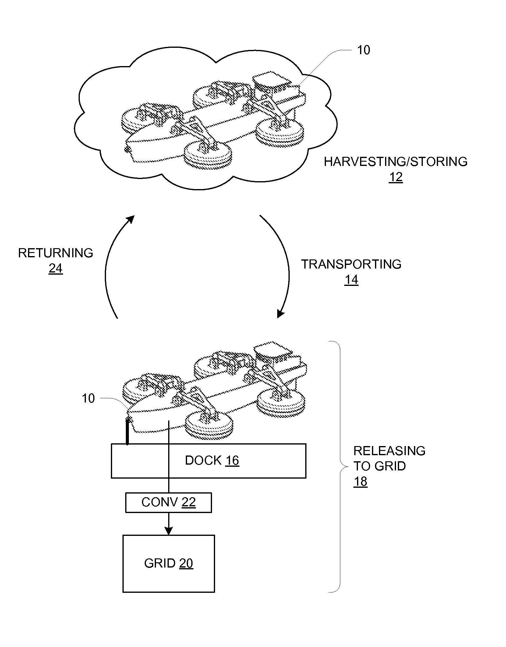
[0028]FIG. 1 depicts a cycle of wave energy harvesting by a ship, barge or similar water vessel 10. The cycle generally has four phases or modes of operating. A wave energy harvesting operation will typically involve indefinite repetitions of this cycle using one or more vessels 10 and other apparatus as more fully described below.

[0029]A harvesting / storing operating mode 12 occurs at a harvesting location on a body of water (e.g., an ocean) subject to wave activity. During the harvesting / storing mode 12, wave energy is absorbed and converted into stored energy in some form, for example as electrochemical energy in an electrical battery on the vessel 10. The vessel 10 may itself include wave energy harvesting apparatus, as more fully described below, or it may contain only storage and be coupled to a separate wave energy harvesting device which is located, either permanently or temporarily, at the harvesting location.

[0030]A transporting mode 14 involves the vessel 10 traveling (e.g...


PUM


Abstract

A system employs wave energy harvesting apparatus and a water vessel (e.g., a ship) carrying an energy storage apparatus (e.g., array of batteries). The energy harvesting apparatus is preferably also carried by the water vessel, but may be fixed or carried by a separate water vessel. The water vessel is operated in an energy storing mode at an energy harvesting location subject to wave activity, during which the energy storage apparatus stores energy from the wave activity as harvested by the energy harvesting apparatus. The water vessel is operated in an energy transporting mode to transport the stored energy from the energy harvesting location to an energy releasing location (preferably onshore, but may be offshore) having a connection to an electrical power grid. The water vessel is operated at the energy releasing location in an energy releasing mode in which the stored energy is transformed into appropriate AC electricity supplied to the electrical power grid.

Description

CROSS-REFERENCE TO RELATED APPLICATIONS[0001]This application is the National Stage of International Application No. PCT / US2010 / 056403, filed on Nov. 11, 2010, which claims the priority of U.S. Provisional Application No. 61 / 260,105 filed on Nov. 11, 2009, the contents of which are incorporated herein by reference in their entirety.BACKGROUND[0002]The present invention is related to the field of energy, and in particular to the field of renewable energy.[0003]The world's oceans produce an enormous amount of wave energy which could potentially provide clean, renewable, and inexpensive electric power. Furthermore, off-shore winds are substantial.[0004]There exist a variety of design concepts for harvesting energy from ocean waves, which can be roughly arranged into several categories. Wave storage devices store energy in reservoirs, and then draw from the reservoir to produce electric power. Wave energy devices convert the energy of a wave directly into electricity, without storage. P...

Claims


Application Information

Patent Timeline
IPC IPC(8): F03B13/10B63B35/44F03B13/18
CPCF03B13/1815B63B35/44B63B2035/4466F05B2240/40F05B2240/931Y02E10/38F03B13/20Y02E10/20Y02E10/30F03B13/14F03B17/02
Inventor SHARON, ANDREWIRZ, HOLGERBRIGGS, JOHN C.HARTMAN, WILLIAMKLOCKE, FRITZ
Owner FRAUNHOFER USA
Why Eureka
Try Eureka