ESD power clamp with stable power start up function

a technology of power start-up function and power clamp, which is applied in the direction of emergency protective arrangements for limiting excess voltage/current, emergency protective arrangements for automatic disconnection, electrical equipment, etc., can solve the problems of incomplete failure of integrated circuit, reduced reliability, and damage to integrated circuits, so as to improve the trigger behavior of esd circuits and achieve high rc time constant , the effect of efficiently “amplifying

Inactive Publication Date: 2015-03-03
GLOBALFOUNDRIES INC
View PDF11 Cites 7 Cited by
  • Summary
  • Abstract
  • Description
  • Claims
  • Application Information

AI Technical Summary

Benefits of technology

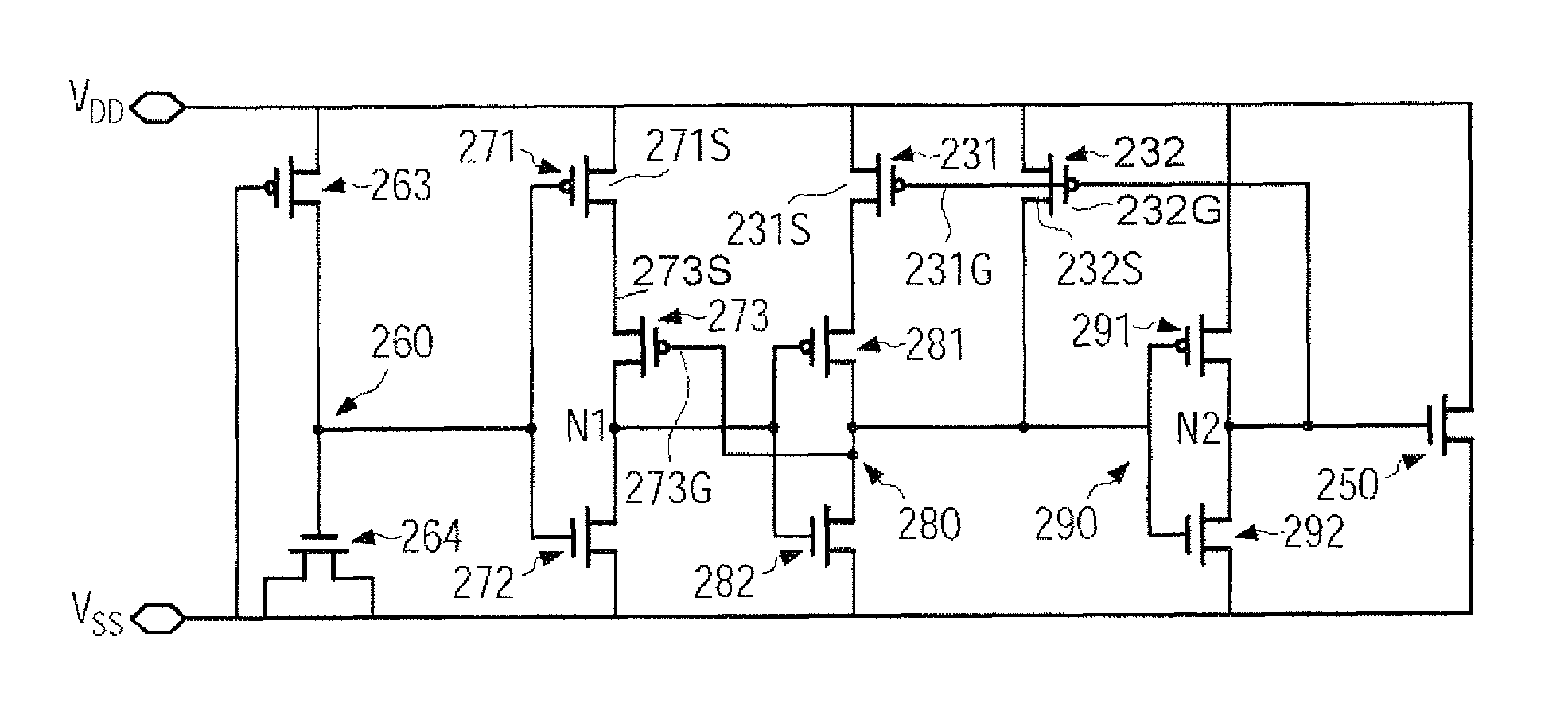
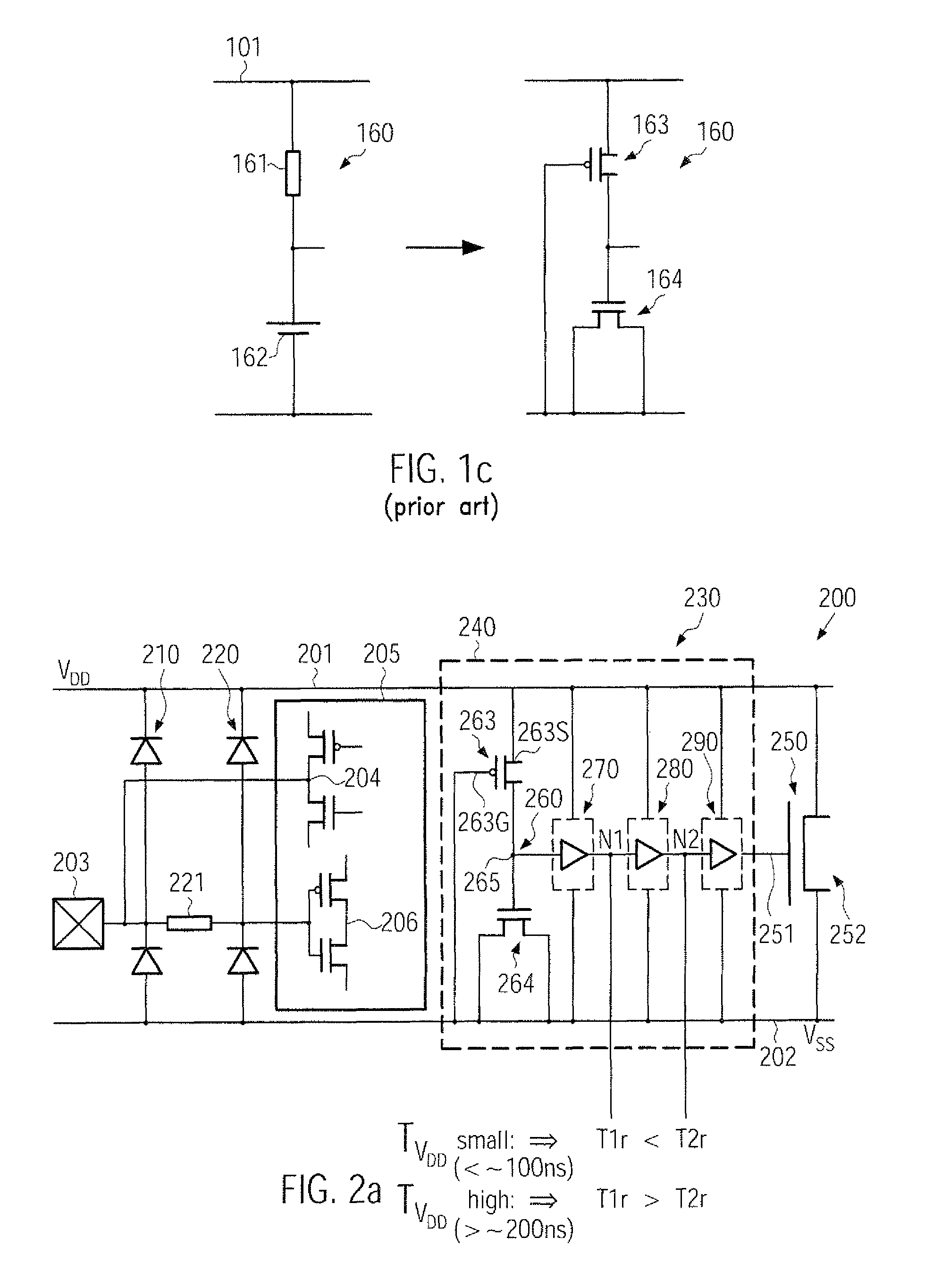
[0014]Generally, the subject matter disclosed herein relates to techniques and electronic circuits in which area-efficient CMOS designs may be used in providing an efficient rail-based ESD protection circuit, that is, resistors may be replaced by field effect transistors, while, nevertheless, providing an improved trigger behavior of the ESD circuit during power up situations. To this end, the inverter stages used in the trigger circuit may be appropriately modified compared to conventional strategies to provide a different response to a fast rising “supply voltage” and a slowly rising normal supply voltage during an initial phase of an ESD situation or a power up, when an “RC” component comprised of field effect transistors may exhibit a moderately high RC time constant. In some illustrative aspects disclosed herein, this imbalance in the response of the inverter stages to the rising supply voltage may be efficiently “amplified” by providing a positive feedback from the second inverter stage to the first inverter stage, thereby reliably “clamping” the respective output nodes of these inverters to obtain the desired trigger behavior. Hence, erroneous trigger events during a power up situation may be avoided or at least substantially reduced.

Problems solved by technology

Any over-voltage supplied to the thin gate insulation layer, however, will lead to defects in the gate insulation layer, resulting in reduced reliability, or to destruction, possibly resulting in a complete failure of the integrated circuit.
For example, a person can develop very high static voltage from a few hundred to several thousand volts, merely by moving across a carpet, so that an integrated circuit may be damaged when the person contacts the integrated circuit, for example, by removing the integrated circuit from the corresponding circuit board.
A corresponding over-voltage caused by an ESD event may even occur during the manufacturing of the integrated circuit and may thus lead to a reduced product yield.
Typically, the NMOS transistor element may be operated during an ESD event by using the parasitic bipolar transistor, which, however, may, in sophisticated CMOS technologies, require significant efforts in obtaining sufficient current drive capabilities of the respective parasitic components.
Therefore, the design of appropriate ESD protection circuits using the pad-based approach may be less flexible with respect to portability to different manufacturing technologies.
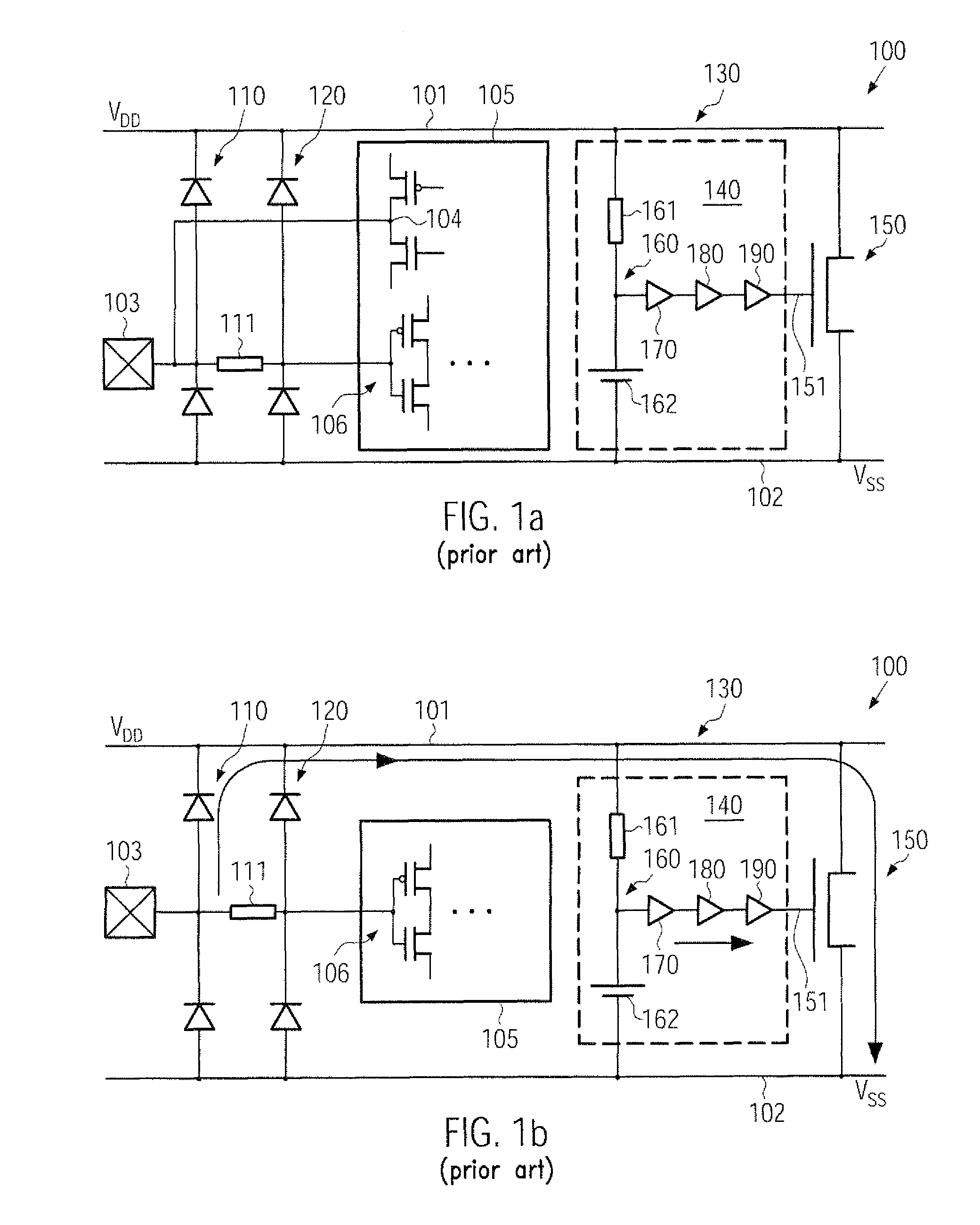
However, although significant advantages with respect to design flexibility and independence of technological characteristics may be provided by the rail-based approach, in certain approaches, the high probability of creating erroneous trigger situations may occur, which will be explained in more detail with reference to FIGS. 1a-1c.
Thus, during power up events of the device 100, a significant current may be drawn by the power clamp transistor 150, which may significantly reduce overall performance of the device 100 in view of settling time and overall power consumption, while also requiring an increase current drive capability of a power source for supplying the circuit 100.

Method used


Image

  • ESD power clamp with stable power start up function
  • ESD power clamp with stable power start up function
  • ESD power clamp with stable power start up function

Examples


Embodiment Construction

[0027]Various illustrative embodiments are described below. In the interest of clarity, not all features of an actual implementation are described in this specification. It will of course be appreciated that in the development of any such actual embodiment, numerous implementation-specific decisions must be made to achieve the developers' specific goals, such as compliance with system-related and business-related constraints, which will vary from one implementation to another. Moreover, it will be appreciated that such a development effort might be complex and time-consuming, but would nevertheless be a routine undertaking for those of ordinary skill in the art having the benefit of this disclosure.

[0028]The present subject matter will now be described with reference to the attached figures. Various structures, systems and devices are schematically depicted in the drawings for purposes of explanation only and so as to not obscure the present disclosure with details that are well kno...


PUM


Abstract

An integrated circuit including a first power rail, a second power rail, a power clamp connected between the first and second power rails; and a trigger circuit connected to the power clamp and the first second power rails. The trigger circuit includes an RC element formed on the basis of field effect transistors, first inverter stage connected to the RC element, a second inverter stage, and a third inverter stage. The first, second and third inverter stages are connected in series to a control input of the power clamp. The trigger circuit also included a feed back connection from an output of the second inverter stage to the first inverter stage.

Description

BACKGROUND[0001]1. Field of the Disclosure[0002]The present disclosure generally relates to the field of integrated circuits having an internal circuitry and a protection circuit to minimize the risk of damage due to electrostatic discharge (ESD) events.[0003]2. Description of the Related Art[0004]In modern integrated circuits usually a very large number of individual circuit elements, such as field effect transistors, capacitors, resistors and the like are formed on a small substrate area to provide the required functionality of the circuitry. Typically, a number of contact pads are provided, which, in turn, are electrically connected to respective terminals, also referred to as pins, to allow the circuitry to communicate with the environment to provide the required input / output (I / O) capabilities. As feature sizes of the circuit elements are steadily shrinking to increase packing density and enhance performance of the integrated circuit, the ability for withstanding an externally ...

Claims


Application Information

Patent Timeline
Patent Type & Authority Patents(United States)
IPC IPC(8): H01L29/66H01L23/62H01L27/02
CPCH01L27/0285
Inventor CHALAMALA, SREENIVASABAER, MATTHIAS
Owner GLOBALFOUNDRIES INC
Why Eureka
Try Eureka