Biodegradable resin container with a vacuum-evaporated film and method of forming a vacuum-evaporated film
a biodegradable resin and vacuum-evaporated film technology, applied in bio-packaging, sustainable manufacturing/processing, applications, etc., can solve the problems of offensive odor generation, thermal deformation of the container wall, thermal degradation of the wall surface, etc., to achieve low glass transition point, low heat resistance, and effective avoidance of thermal deformation
- Summary
- Abstract
- Description
- Claims
- Application Information
AI Technical Summary
Benefits of technology
Problems solved by technology
Method used
Image

Examples
examples
[0075]The invention will be described next by Examples.
[0076]Described below are bottles for testing the vacuum evaporation, method of evaluating properties of the bottles and method of analyzing the vacuum-evaporated films used in the following Examples and Comparative Examples.
(Containers for Testing Vacuum Evaporation)
[0077]Polylactic acid bottles having a capacity of 400 ml obtained by biaxially draw-blow forming the polylactic acid (PLA) resin preforms.
(Vacuum Evaporation Treatment)
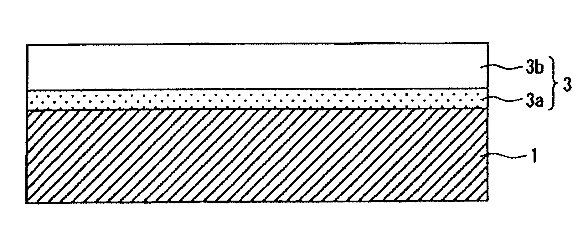
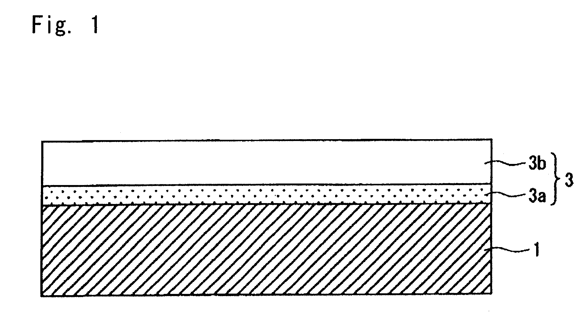
1. First Hydrocarbon Vacuum-Evaporated Layer (3a).
[0078]A biodegradable resin bottle on which a film is to be formed was disposed in a chamber. In a state where the interior and exterior of the bottle have been evacuated down to a predetermined vacuum degree in the chamber, a starting gas or a reactive gas which is a mixture of a hydrocarbon compound gas (acetylene) and a polar group-containing organic compound gas (ethanol, etc.) at a ratio of 150:1 to 8:1 (total amount of gas, 30 sccm) was introduc...
example
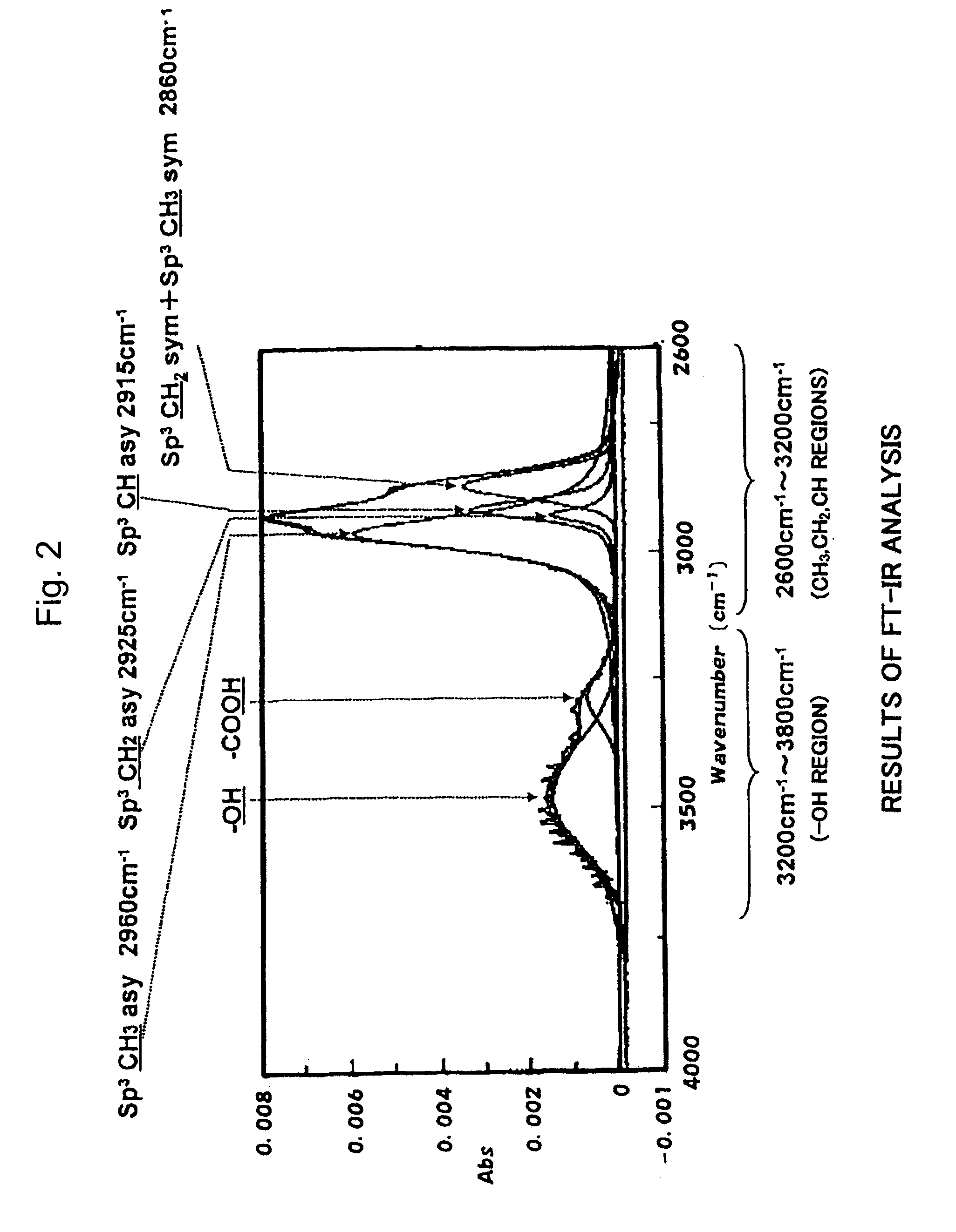
Methyl Structure
[0090]
CH3(%)=I(CH3) / {I(CH3)+I(CH2)+I(CH)}·100
I(CH3)=(CH3: 2960 cm−1) curve-fitting value×absorbency coefficient (0.31)
I(CH2)=(CH2: 2925 cm−1) curve-fitting value×absorbency coefficient (0.29)
I(CH)=(CH: 2915 cm−1) curve-fitting value×absorbency coefficient (0.14) (1)
(Measurement of the Amount of Polar Groups)
[0091]The infrared absorption peaks of the OH groups over 3200 cm−1 to 3800 cm−1 were not corrected by absorbency coefficients, but the observed peak intensities were used. The sum of a peak intensity between (2600 cm−1 and 3200 cm−1) and a peak intensity between (3200 cm−1 and 3800 cm−1) was used as a denominator and the peak intensity of (3200 cm−1 and 3800 cm−1) was used as a numerator to thereby calculate a relative amount of OH groups (%).
[0092](Measurement of Film Thickness)
[0093]In vacuum evaporating the film on the test bottles, silicon wafers measuring 20 mm×20 mm were inserted and attached to the inner surfaces of the bottles, and the films were vacuum-...
PUM
| Property | Measurement | Unit |
|---|---|---|
| thickness | aaaaa | aaaaa |
| thickness | aaaaa | aaaaa |
| Tg | aaaaa | aaaaa |
Abstract
Description
Claims
Application Information
 - R&D
- Intellectual Property
- Life Sciences
- Materials
- Tech Scout
- Unparalleled Data Quality
- Higher Quality Content
- 60% Fewer Hallucinations
Browse by: Latest US Patents, China's latest patents, Technical Efficacy Thesaurus, Application Domain, Technology Topic, Popular Technical Reports.
© 2025 PatSnap. All rights reserved.Legal|Privacy policy|Modern Slavery Act Transparency Statement|Sitemap|About US| Contact US: help@patsnap.com