
Physically unclonable functions based on non-linearity of sub-threshold operation

a function and non-linearity technology, applied in the field of physical unclonable functions, can solve the problems of pufs showing a vulnerability to machine-learning attacks, different mapping between challenges and responses implemented by the circuit,

Inactive Publication Date: 2015-01-20
BOARD OF RGT THE UNIV OF TEXAS SYST
View PDF10 Cites 10 Cited by
  • Summary
  • Abstract
  • Description
  • Claims
  • Application Information

AI Technical Summary

Benefits of technology

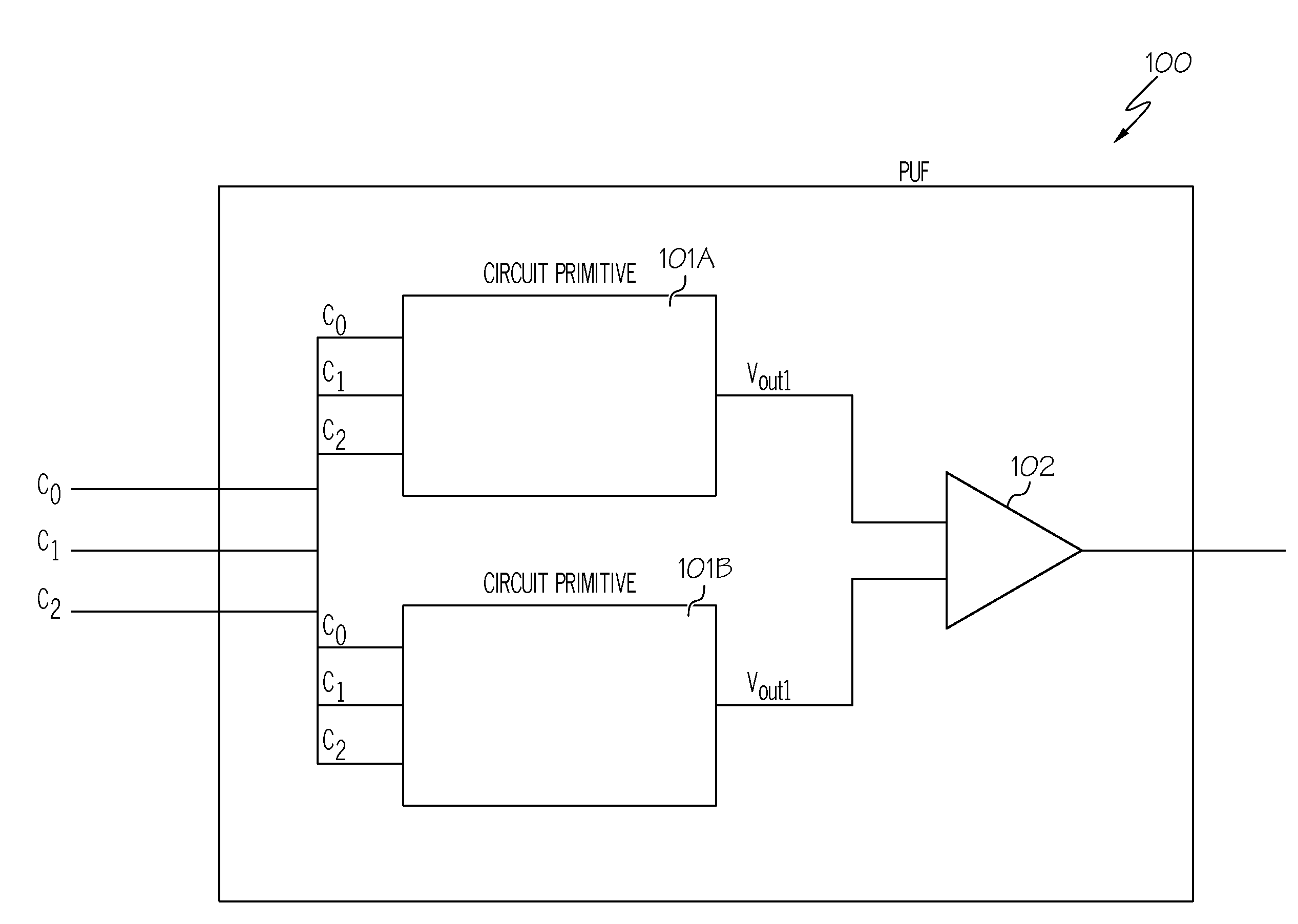
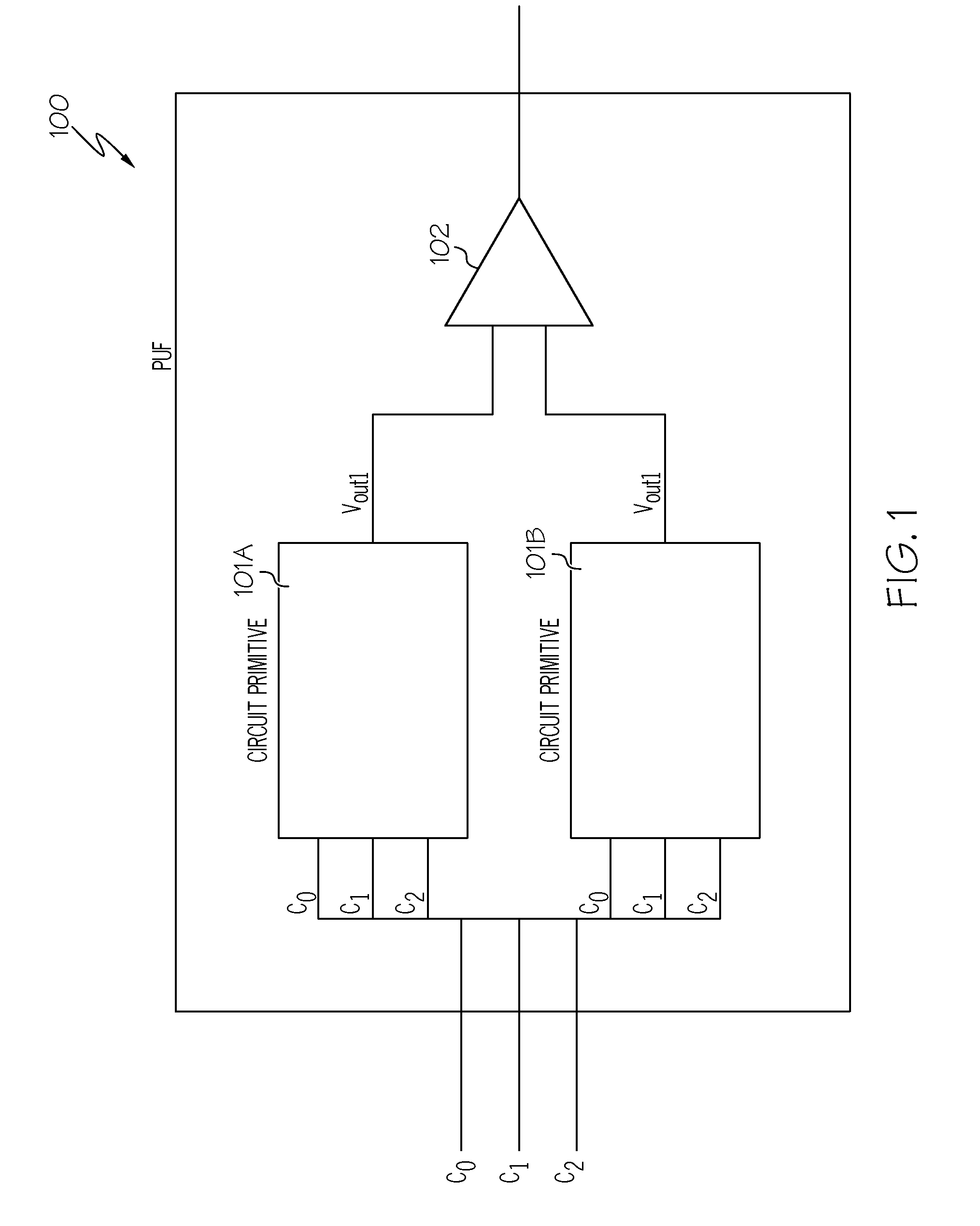
The present invention describes an electronic circuit that can produce an output based on a difference between two input values. The circuit has a unique structure that includes two copies of a circuit block, each containing at least one transistor in a sub-threshold region. The circuit also includes a comparator to compare the output of the two blocks and generate the output based on the difference between them. The circuit is designed to be challenged with a binary value to produce a unique output for each challenge. The technical effects of this invention include the ability to produce a secure and reliable output based on the unique structure of the circuit, which is difficult to replicate or alter. Additionally, the invention allows for the protection of sensitive information within the circuit, as the output is based on the current flow through the transistors, which is affected by threshold voltage variations.

Problems solved by technology

When a circuit with the same layout mask is fabricated to result in different chips, the mapping between challenges and responses implemented by the circuit is different for each chip due to the random variations of delays.
Unfortunately, such PUFs show a vulnerability to machine-learning attacks due to the linear separability of the output function as a result of the additive nature of the timing delay along the paths.

Method used


Image

  • Physically unclonable functions based on non-linearity of sub-threshold operation
  • Physically unclonable functions based on non-linearity of sub-threshold operation
  • Physically unclonable functions based on non-linearity of sub-threshold operation

Examples


Embodiment Construction

[0014]In the following description, numerous specific details are set forth to provide a thorough understanding of the present invention. However, it will be apparent to those skilled in the art that the present invention may be practiced without such specific details. In other instances, well-known circuits have been shown in block diagram form in order not to obscure the present invention in unnecessary detail. For the most part, details considering timing considerations and the like have been omitted inasmuch as such details are not necessary to obtain a complete understanding of the present invention and are within the skills of persons of ordinary skill in the relevant art.

[0015]As stated in the Background section, currently, the most widely adopted strong silicon-based PUFs (those with a large number of challenge-response pairs) are based on establishing timing races and relying on arbiters to produce a rich set of responses. The PUF circuit can use random variations in the de...


PUM


Abstract

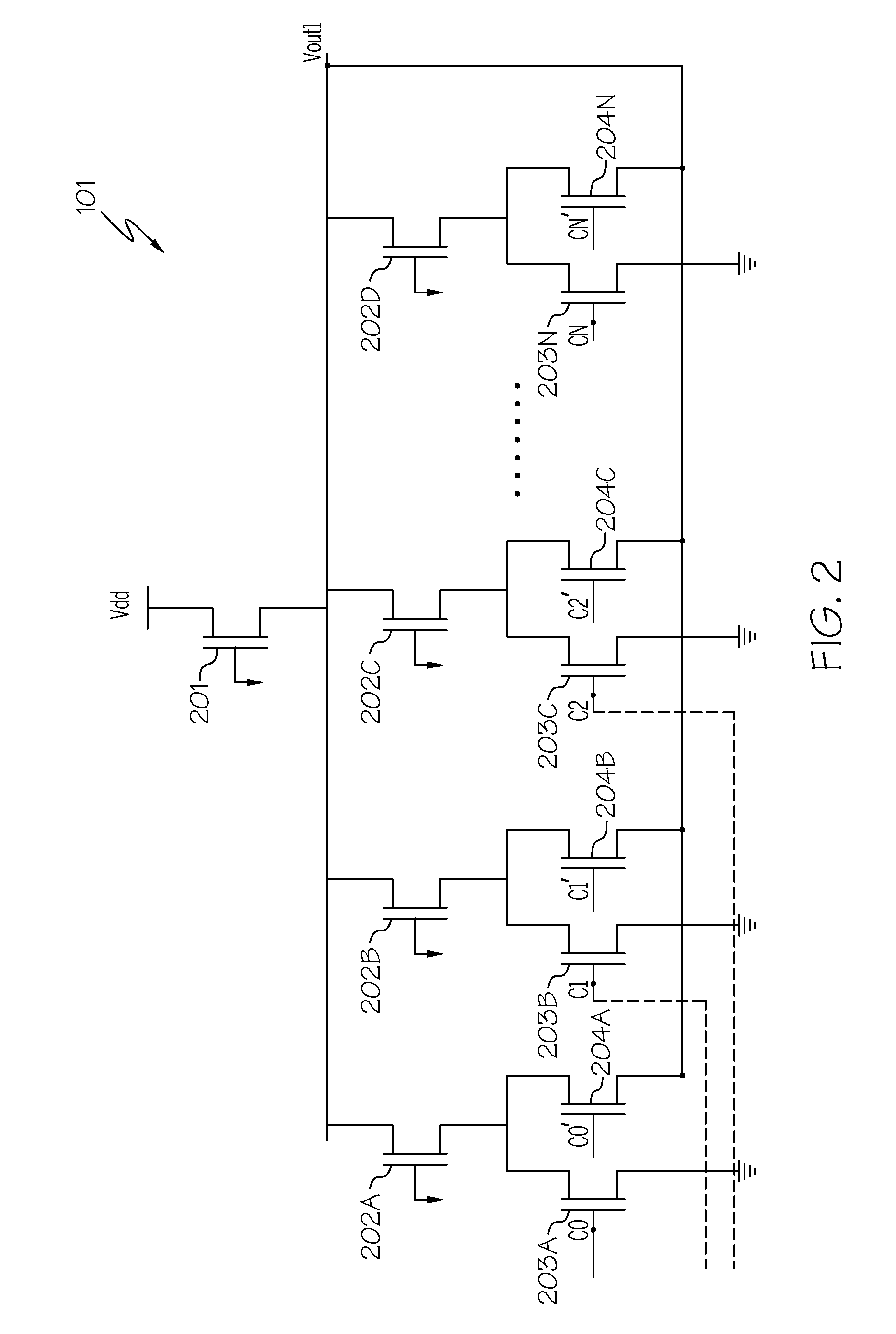
An electronic circuit for implementing a physically unclonable function. The electronic circuit includes duplicate circuits, referred to as “circuit primitives,” that generate a first and a second output voltage based on the received input, referred to as a “challenge.” The electronic circuit further includes a comparator coupled to the circuit primitives and generates an output based on the difference between the first and second output voltages. While the circuit primitives contain duplicate circuitry, the circuit primitives may generate a different output voltage due to a particular set of transistors in the circuit primitives operating in the sub-threshold region whose gates are tied to ground and whose sub-threshold current, the magnitude of which is random based on the threshold voltage variation of the set of transistors, is used to affect the value of the output voltage.

Description

CROSS-REFERENCE TO RELATED APPLICATIONS[0001]This application is related to the following commonly owned U.S. Patent Application:[0002]Provisional Application Ser. No. 61 / 655,689, “Physically Unclonable Functions Based on Non-Linearity of Sub-Threshold Operation and Drain-Induced Barrier Lowering Effect,” filed Jun. 5, 2012, and claims the benefit of its earlier filing date under 35 U.S.C. §119(e).TECHNICAL FIELD[0003]The present invention relates generally to physically unclonable functions, and more particularly to highly secure strong Physically Unclonable Functions (PUFs) based on the strong non-linearity of the Field-Effect Transistor (FET) operation in the sub-threshold region and the Drain-Induced Barrier Lowering (DIBL) effect.BACKGROUND[0004]A Physically Unclonable Function (PUF) exploits variations, such as stochastic process variations in manufacturing, to generate secret keys used in cryptographic operations, chip authentication, and even random number generation. A devi...

Claims


Application Information

Patent Timeline
Patent Type & Authority Patents(United States)
IPC IPC(8): H04L9/32H04L9/00H04L9/06H04L9/18H04L9/08H04L29/06
CPCH04L9/3278H04L9/18H04L9/08H04L9/06H04L9/00
Inventor ORSHANSKY, MICHAEL
Owner BOARD OF RGT THE UNIV OF TEXAS SYST
Learn More