
Systems for Coarse/Fine Program Verification in Non-Volatile Memory Using Different Reference Levels for Improved Sensing

a non-volatile memory and reference level technology, applied in static storage, digital storage, instruments, etc., can solve the problem of increasing the total time needed to program memory cells, and achieve the effect of accurate threshold voltage sensing

Inactive Publication Date: 2009-01-08
SANDISK TECH LLC
View PDF87 Cites 44 Cited by
  • Summary
  • Abstract
  • Description
  • Claims
  • Application Information

AI Technical Summary

Benefits of technology

[0021]The technology described herein attempts to provide a more accurate sensing of the threshold voltage of non-volatile storage elements during programming verification when coarse / fine programming is utilized.
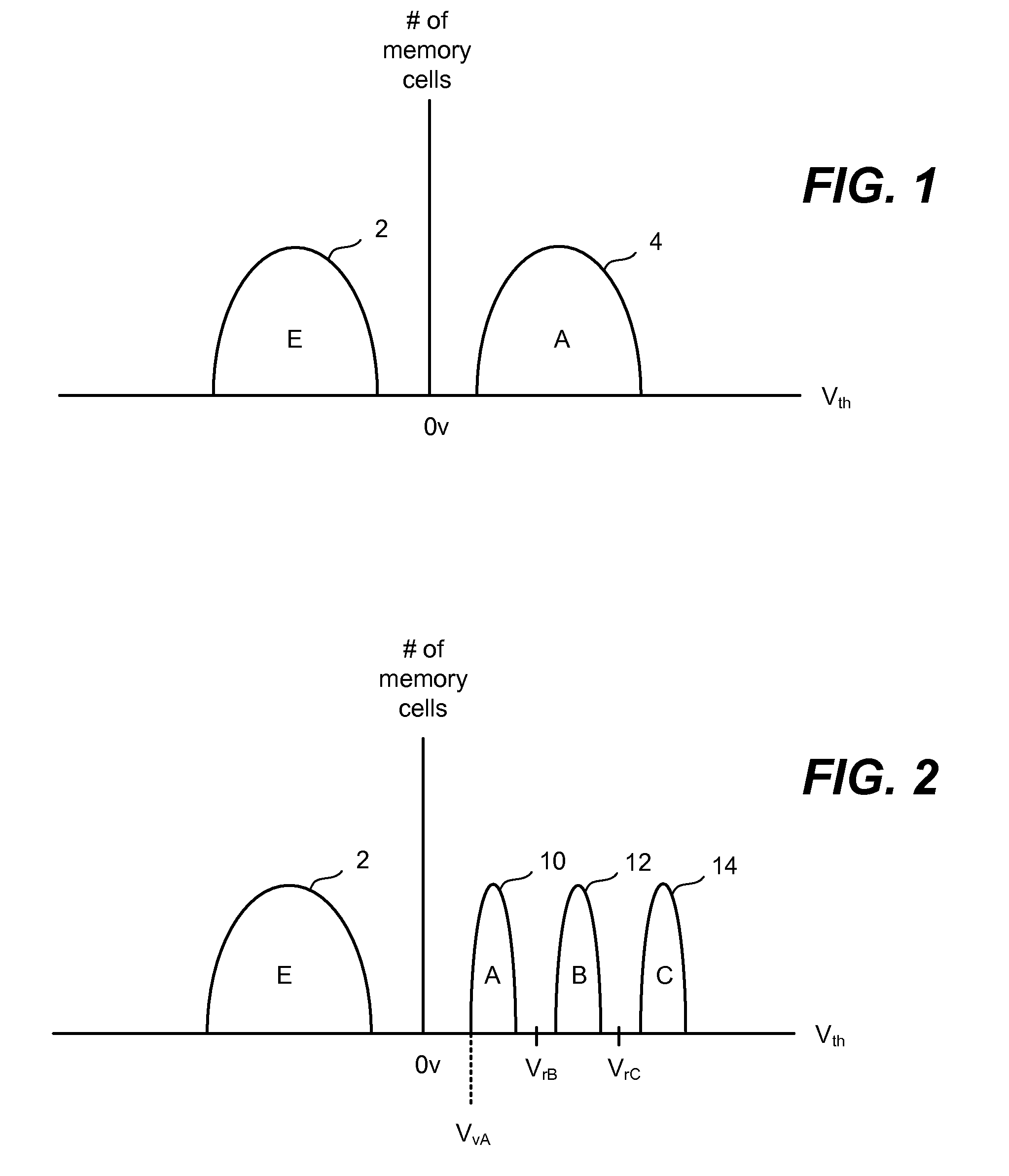
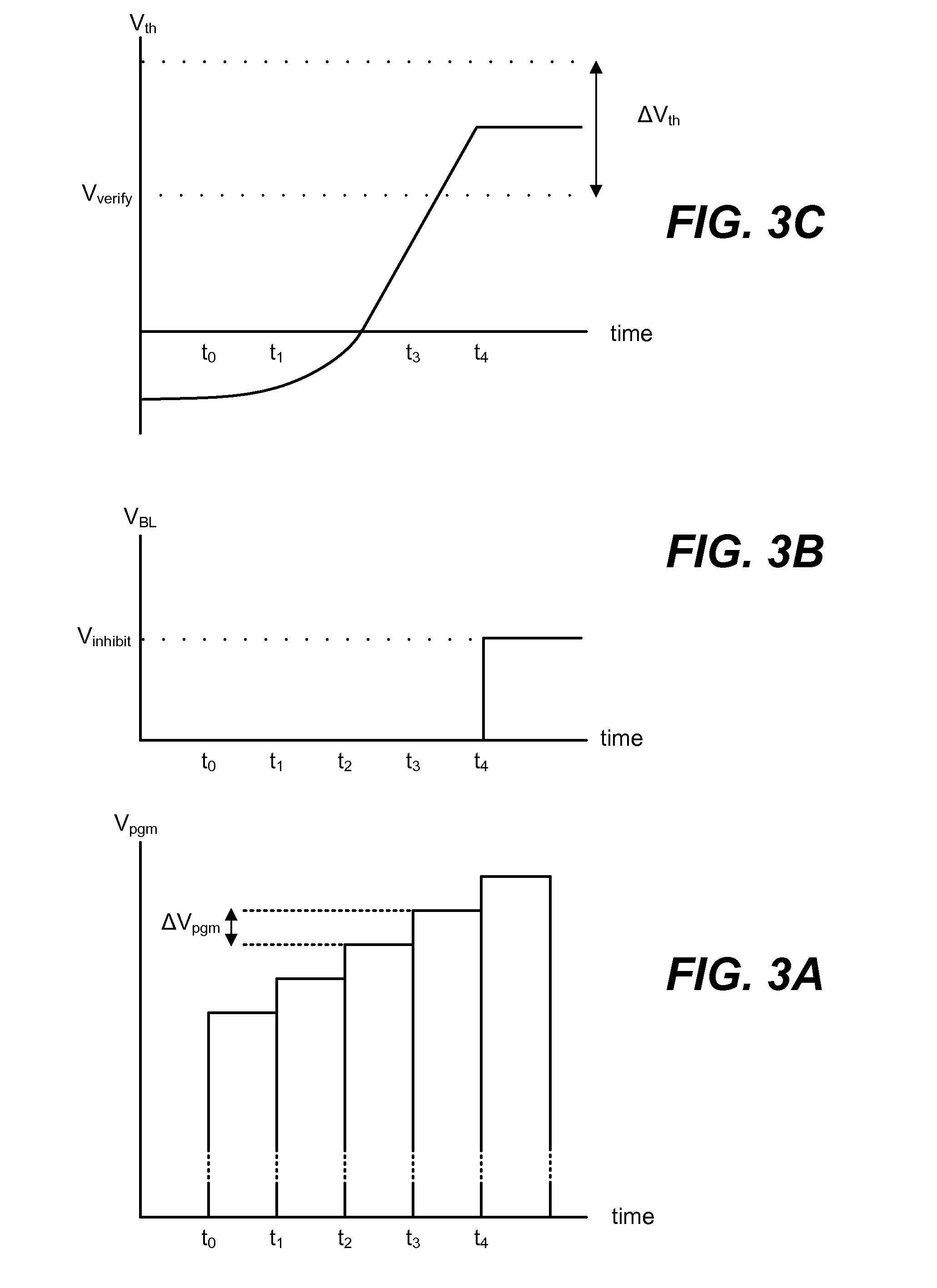
[0022]Coarse / fine programming of non-volatile memory is provided in which memory cells are programmed at a first rate of programming prior to reaching a coarse verify level for their intended state and a second rate of programming after reaching the coarse verify level but before reaching the final verify level for their intended state. Large sub-threshold swing factors associated with smaller memory cells can affect the accuracy of sense operations, particularly when sensing at a fine verify level after sensing at a coarse verify level without pre-charging the bit line between the different sensings. Different reference potentials are utilized when sensing at a coarse verify level and a final verify level. The difference between the reference potentials can compensate for any discharge of the bit line during the coarse level sensing.

Problems solved by technology

This may increase the total time needed to program the memory cells.
However, some implementations will make use of coarse / fine programming techniques when programming the highest level state as well.

Method used


Image

  • Systems for Coarse/Fine Program Verification in Non-Volatile Memory Using Different Reference Levels for Improved Sensing
  • Systems for Coarse/Fine Program Verification in Non-Volatile Memory Using Different Reference Levels for Improved Sensing
  • Systems for Coarse/Fine Program Verification in Non-Volatile Memory Using Different Reference Levels for Improved Sensing

Examples


Embodiment Construction

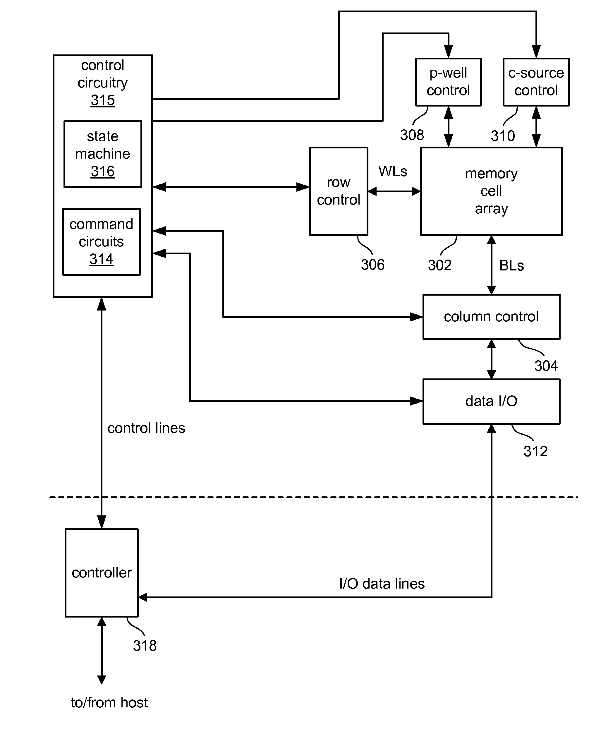
[0046]One example of a flash memory system suitable for implementing embodiments of the present disclosure uses the NAND structure, which includes multiple transistors arranged in series between two select gates. The transistors in series and the select gates are referred to as a NAND string. FIG. 6 is a top view showing one NAND string. FIG. 7 is an equivalent circuit thereof. The NAND string depicted in FIGS. 5 and 6 includes four transistors 100, 102, 104 and 106 in series and sandwiched between a select gate 120 and a second select gate 122. Select gate 120 connects the NAND string to bit line contact 126. Select gate 122 connects the NAND string to source line contact 128. Select gate 120 is controlled by the applying appropriate voltages to control gate 120CG. Select gate 122 is controlled by applying the appropriate voltages to control gate 122CG. Each of the transistors 100, 102, 104 and 106 has a control gate and a floating gate. Transistor 100 has control gate 100CG and fl...


PUM


Abstract

Coarse / fine programming of non-volatile memory is provided in which memory cells are programmed at a first rate of programming prior to reaching a coarse verify level for their intended state and a second rate of programming after reaching the coarse verify level but before reaching the final verify level for their intended state. Large sub-threshold swing factors associated with smaller memory cells can affect the accuracy of sense operations, particularly when sensing at a fine verify level after sensing at a coarse verify level without pre-charging the bit line between the different sensings. Different reference potentials are utilized when sensing at a coarse verify level and a final verify level. The different between the reference potentials can compensate for any discharge of the bit line during the coarse level sensing.

Description

CROSS-REFERENCE TO RELATED APPLICATIONS[0001]The following application is cross-referenced and incorporated by reference herein in its entirety:[0002]U.S. patent application Ser. No. ______ [Attorney Docket No. SAND-01145US0], entitled “Coarse / Fine Program Verification in Non-Volatile Memory Using Different Reference Levels for Improved Sensing,” by Shih-Chung Lee, filed concurrently.BACKGROUND OF THE INVENTION[0003]1. Field of the Invention[0004]The present disclosure relates to programming in non-volatile memory.[0005]2. Description of the Related Art[0006]Semiconductor memory devices have become more popular for use in various electronic devices. For example, non-volatile semiconductor memory is used in cellular telephones, digital cameras, personal digital assistants, mobile computing devices, non-mobile computing devices and other devices. Electrical Erasable Programmable Read Only Memory (EEPROM), including flash EEPROM, and Electronically Programmable Read Only Memory (EPROM)...

Claims


Application Information

Patent Timeline
Patent Type & Authority Applications(United States)
IPC IPC(8): G11C11/34G11C16/06
CPCG11C11/5628G11C11/5642G11C2211/5634G11C16/3454G11C2211/5621G11C16/0483
Inventor LEE, SHIH-CHUNG
Owner SANDISK TECH LLC
Learn More