Annular combustion chamber of a turbomachine
a turbomachine and combustion chamber technology, applied in the direction of liquid fuel engines, couplings, lighting and heating apparatus, etc., can solve problems such as weakening of the combustion chamber, and achieve the effect of reducing the leakage of combustion gas and improving the mechanical strength of the assembly
- Summary
- Abstract
- Description
- Claims
- Application Information
AI Technical Summary
Benefits of technology
Problems solved by technology
Method used
Image
Examples
first embodiment
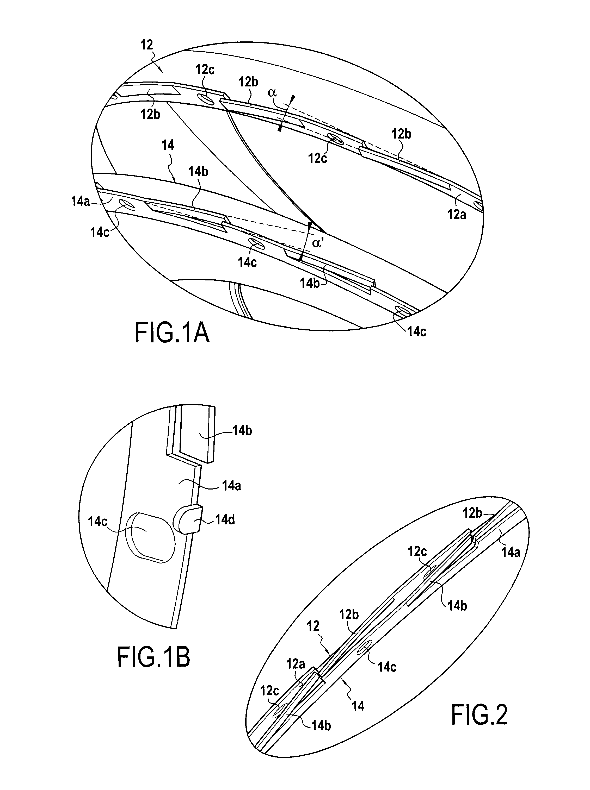
[0050]FIGS. 1, 1A, 1B, 2, 3, 4A, and 4B show the combustion chamber of the invention corresponding to the first above-mentioned variant. The combustion chamber 10 has a first annular wall 12 and a second annular wall 14. The combustion chamber 10 presents an axial direction X (along the axis X), a radial direction R, and an azimuth direction Y. The combustion chamber 10 presents symmetry of revolution about the axis X. In this example, the first wall 12 is the outer casing of the flame tube 50, which tube also has an inner casing 16 and a chamber end wall 18. The flame tube 50 receives fuel injectors 52 and it defines the enclosure in which the fuel is burned, i.e. where combustion takes place. The second wall 14 forms an outer bend and serves as a deflector for guiding the flow of gas coming from the flame tube 50. It should be observed that this combustion chamber 10 is an annular chamber of the reverse flow type, however the invention is not limited to this particular type of com...
second embodiment
[0059]The blocking means of the combustion chamber 110 in the invention correspond firstly to a number P of first projections 112 secured to the first wall 12, and secondly to the same number P of second projections 114 secured to the second wall 14. In this example, there are eighteen first and second projections, i.e. P=18. More particularly, the first projections 112 extend radially from the first annular flange 12a, while the second projections 114 extend radially from the second annular flange 14a. Each first and second projection 112 and 114 forms a hook having an L-shaped profile, the top of the vertical bar of the L-shape being connected to the corresponding annular flange, while the horizontal bar of the L-shape extends axially. The plate 112a and 114a formed by the horizontal bar of the L-shaped hook of each projection 112 and 114 is inclined at a respective angle β and β′ relative to the azimuth direction (cf. FIG. 4A), the plates 112a and 114a of the first and second pro...
third embodiment
[0064]The blocking means of the combustion chamber 210 in the invention comprise firstly a number Q of foldable blades 212 formed in the first flange 12a, and secondly the same number Q of gaps 214 formed in the second flange 14a. In this example, there are eighteen blades and gaps, i.e. Q=18. The gaps 214 are U-shaped, opening out to the outer periphery of the flange 14a. Naturally, in a variant, the gaps could be provided in the first flange, while the foldable blades could be formed in the second flange. The foldable blades form the first blocking means, while the gaps form the second blocking means, and they may naturally be provided in different numbers.
[0065]FIGS. 6A and 6B show two relative positions of foldable blades 212 relative to gaps 214 while the first and second tongues are being engaged in azimuth. When the second wall 14 is caused to pivot about the axis X in order to engage the first and second tongues 12b and 14b in the direction of the arrow in FIG. 6A, the gaps ...
PUM
| Property | Measurement | Unit |
|---|---|---|
| degrees of angle | aaaaa | aaaaa |
| angle | aaaaa | aaaaa |
| β=β | aaaaa | aaaaa |
Abstract
Description
Claims
Application Information
 - R&D
- Intellectual Property
- Life Sciences
- Materials
- Tech Scout
- Unparalleled Data Quality
- Higher Quality Content
- 60% Fewer Hallucinations
Browse by: Latest US Patents, China's latest patents, Technical Efficacy Thesaurus, Application Domain, Technology Topic, Popular Technical Reports.
© 2025 PatSnap. All rights reserved.Legal|Privacy policy|Modern Slavery Act Transparency Statement|Sitemap|About US| Contact US: help@patsnap.com


