Hydraulic crowd system for electric mining shovel

a mining shovel and hydraulic technology, applied in the field of mining shovels, can solve the problems of teeth or ropes, prone to breakage of racking teeth and ropes, and inability to rotate,

Active Publication Date: 2014-12-30
CATERPILLAR GLOBAL MINING LLC
View PDF5 Cites 0 Cited by
  • Summary
  • Abstract
  • Description
  • Claims
  • Application Information

AI Technical Summary

Problems solved by technology

For example, the rack teeth and ropes are prone to break when excessive force is applied Furthermore, the handles in rack and pinion mechanism which must remain rotatably fixed, and therefore cannot be rotated.
Further, they do not include rack teeth or ropes, which are prone to break when excessive force is applied While hydraulic mechanisms therefore provide certain advantages over other types of crowd controls, particularly with respect to maintenance, the volume of hydraulic fluid necessary to control the crowd of a mining shovel dipper handle requires complex large hoses, designed to carry a large volume of fluid, and at high pressures.
Because of the high pressure application, these hoses are subject to significant wear, and requiring a significant degree of maintenance.

Method used


Image

  • Hydraulic crowd system for electric mining shovel
  • Hydraulic crowd system for electric mining shovel
  • Hydraulic crowd system for electric mining shovel

Examples


Embodiment Construction

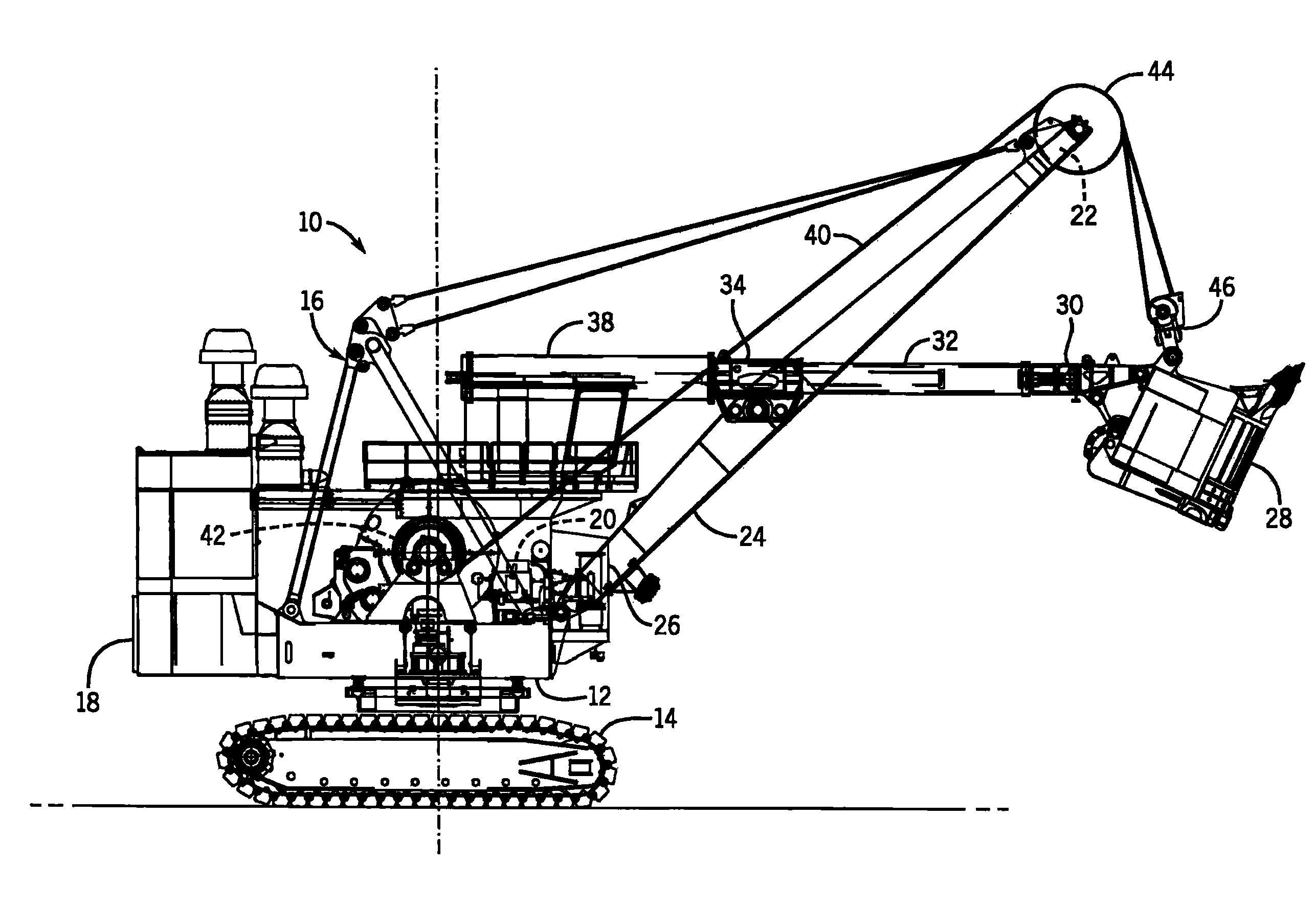
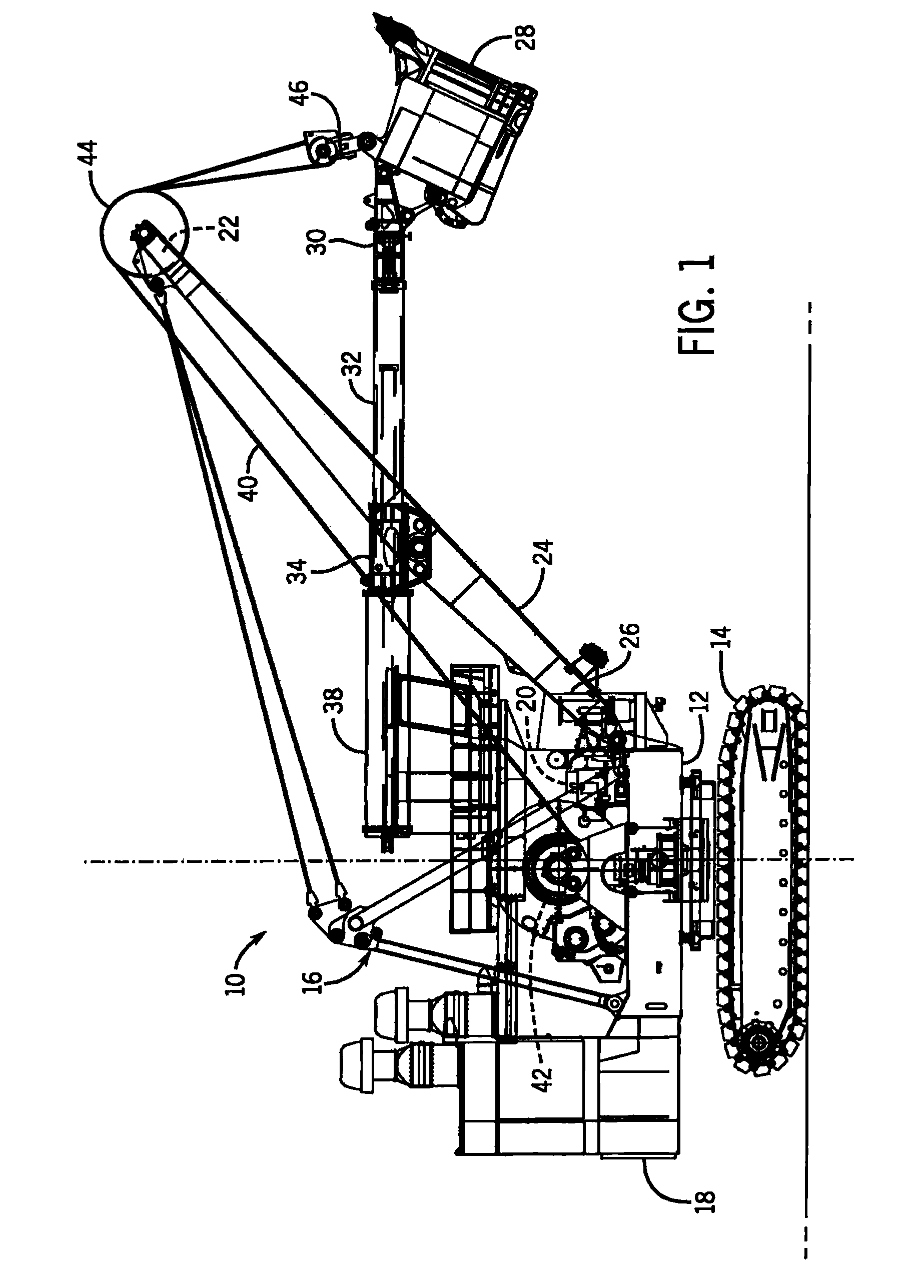
[0023]Referring to FIG. 1, a mining shovel 10 is shown. The mining shovel 10 includes a turntable 12 mounted on a crawler truck 14, and supporting an A-frame 16 and a cab 18. The cab houses a power unit 20, including a hydraulic crowd control system 21 (FIG. 2), and an electrical control system that operates the mining shovel components in response to inputs from the operator and automatic devices, such as limit switches, pressure switches, temperature switches, and the like. The operator can provide inputs from within the cab through manually operable devices, such as a joystick, lever, foot pedals, rocker switches, computer keyboard, touch pads, and the like.

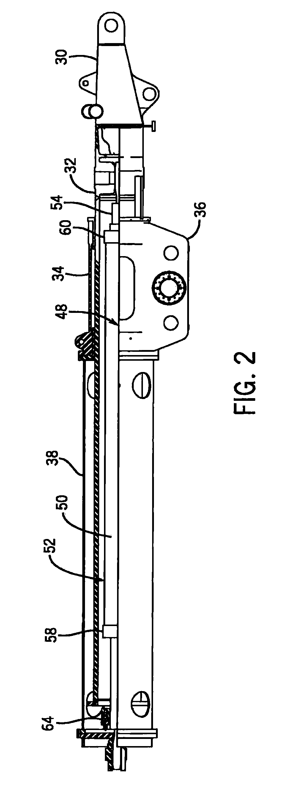
[0024]The A-frame 16 supports a top end 22 of a boom 24, a bottom end 26 of the boom 24 being supported by the turntable 12. A dipper 28 is mounted on the front end 30 of a dipper handle 32 which is slidably supported in a saddle block 34 mounted in the boom 24. The saddle block includes a yoke 36 and a support frame 38 which ...


PUM


Abstract

A mining shovel (10) includes a hydraulic system comprising a plurality of fixed displacement pumps (104,106,108,110) driven by a variable speed motor (100), and a tank (68) system comprising an upper return tank and a lower supply tank (70). A cylinder manifold (64) is connected to the pump control manifold (112), and includes a directional control valve for directing the extend and retract functions of the cylinder (50), while accepting fluid flow in a single direction from the pump control manifold. The single direction flow allows for the use of smaller fluid conduits (61), such that the hose providing a high pressure supply can be comparatively smaller than the return hose (67).

Description

CROSS-REFERENCE TO RELATED APPLICATIONS[0001]The present application is a U.S. national stage of and claims priority to and the benefit of International Application No. PCT / US2009 / 045833, entitled “Hydraulic Crowd System for Electric Mining Shovel,” filed Jun. 1, 2009, which is incorporated herein by reference in its entirety.TECHNICAL FIELD[0002]This invention relates to mining shovels, and more particularly to hydraulic crowd control mechanisms for a mining shovel.DESCRIPTION OF THE BACKGROUND ART[0003]A typical mining shovel includes a turntable mounted on a crawler truck, and supporting an A-frame and a cab. A boom extending from the turntable has an upper end supported by the A-frame. The boom pivotally supports a dipper handle which pivots in a vertical plane. A dipper fixed to a distal end of the dipper handle is raised and lowered by a hoist cable which extends over a sheave at the top of the boom and down to a padlock on the dipper. The hoist cable provides for the vertical...

Claims


Application Information

Patent Timeline
Patent Type & Authority Patents(United States)
IPC IPC(8): E02F9/22E02F3/30
CPCE02F9/2271E02F9/2267E02F3/304
Inventor GILMORE, CARL D.WEBER, ROBERTDECUIR, PERRY
Owner CATERPILLAR GLOBAL MINING LLC
Why Eureka
Try Eureka