
Printing apparatus

a printing apparatus and print head technology, applied in the field of printing apparatuses, can solve the problems of poor contact between the electric contact of the printhead and the electric contact of the carriage, which is not completely solved, and is difficult to solve, so as to reduce the time taken to charge the capacitor and achieve the effect of increasing the speed of contact check and current leakage detection

Active Publication Date: 2014-12-02
CANON KK
View PDF5 Cites 2 Cited by
  • Summary
  • Abstract
  • Description
  • Claims
  • Application Information

AI Technical Summary

Benefits of technology

This patent describes a printing apparatus that can quickly and safely detect if there is a leakage of electric current or if there is a connection between two parts. The apparatus uses a small amount of power and is not designed to damage the printing elements during contact checking or current leakage detection. This allows for a safer and faster process.

Problems solved by technology

In a printing apparatus configured to allow the user to replace a printhead mounted on a carriage, a poor contact between the electric contact of the printhead and the electric contact of the carriage that occurs when the user replaces the printhead has not completely been solved in practice though electric contacts have been improved.
The poor contact occurs when small dust is sandwiched between the electric contact of the printhead and that of the carriage upon replacing the printhead.
Since this problem arises in the apparatus environment, it is difficult to solve this problem regardless of the improvement of the product.
There is also a problem that, as the printhead is used for a long period, a circuit in the printhead goes wrong due to aging of the printhead, and a current leaks from the head voltage supply line, causing poor printing.
For this reason, leakage detection takes time.
In the conventional arrangement in which the capacitor for stabilizing a head voltage is interposed between the printhead and GND, contact detection also requires a long time.
In the conventional arrangement in which contact detection of one electric contact takes time, it is not even practical to implement contact detection in the apparatus.
However, as the number of electric contacts which electrically connect the carriage and the printhead increases, the ratio of poor connections increases.
Since contact detection of the printhead is a necessary function, to implement contact detection in a printing apparatus, increasing the process speed is an urgent matter.
Also, leakage detection requires a high process speed.
If this arrangement is simply applied to contact detection, the printhead may be damaged in poor mounting of the printhead.

Method used


Image

  • Printing apparatus
  • Printing apparatus
  • Printing apparatus

Examples


Embodiment Construction

[0025]An exemplary embodiment of the present invention will now be described in detail in accordance with the accompanying drawings. It should be noted that the relative arrangement of building components and the like set forth in the embodiment do not limit the scope of the present invention unless it is specifically stated otherwise.

[0026]In this specification, the terms “print” and “printing” not only include the formation of significant information such as characters and graphics, but also broadly includes the formation of images, figures, patterns, and the like on a print medium, or the process of the medium, regardless of whether they are significant or insignificant and whether they are so visualized as to be visually perceivable by humans.

[0027]Also, the term “print medium” not only includes a paper sheet used in common printing apparatuses, but also broadly includes materials, such as cloth, a plastic film, a metal plate, glass, ceramics, wood, and leather, capable of accep...


PUM


Abstract

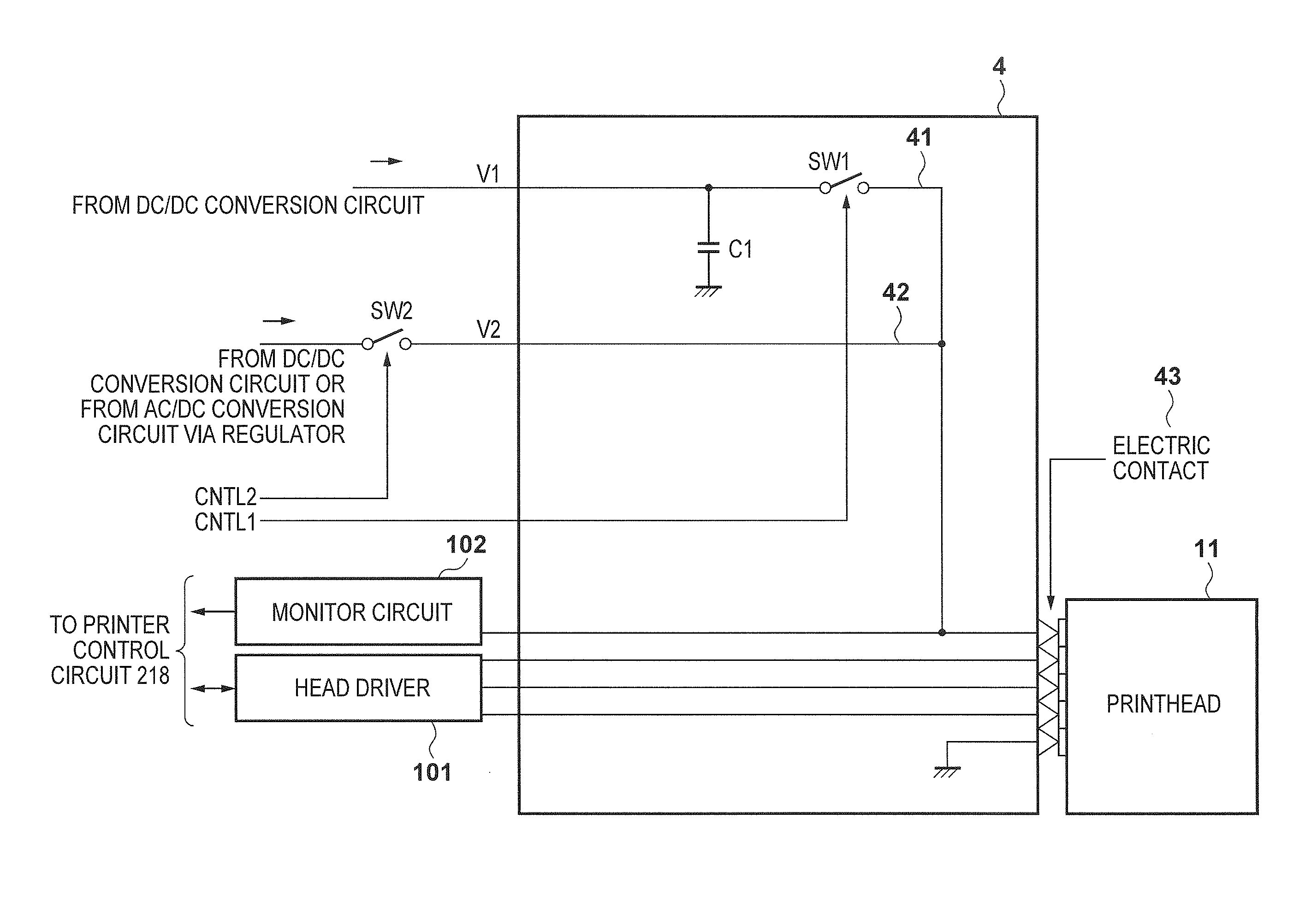
Disclosed is a printing apparatus capable of safe high-speed leakage detection and contact detection of a printhead. The leakage detection and contact detection are executed in the apparatus which prints on a printing medium by scanning a removable printhead mounted to a carriage. When the printhead is mounted, connection with a capacitor used in normal printing is disconnected, a lower voltage is applied to drive a printing element and monitor the voltage. If the monitored voltage is not less than a predetermined threshold, occurrence of a poor contact is determined. This is performed for electric contacts one by one. During the operation, a lower voltage is applied at a predetermined timing to drive a printing element and monitor the voltage. If the monitor voltage is not higher than a predetermined threshold, occurrence of current leakage is determined.

Description

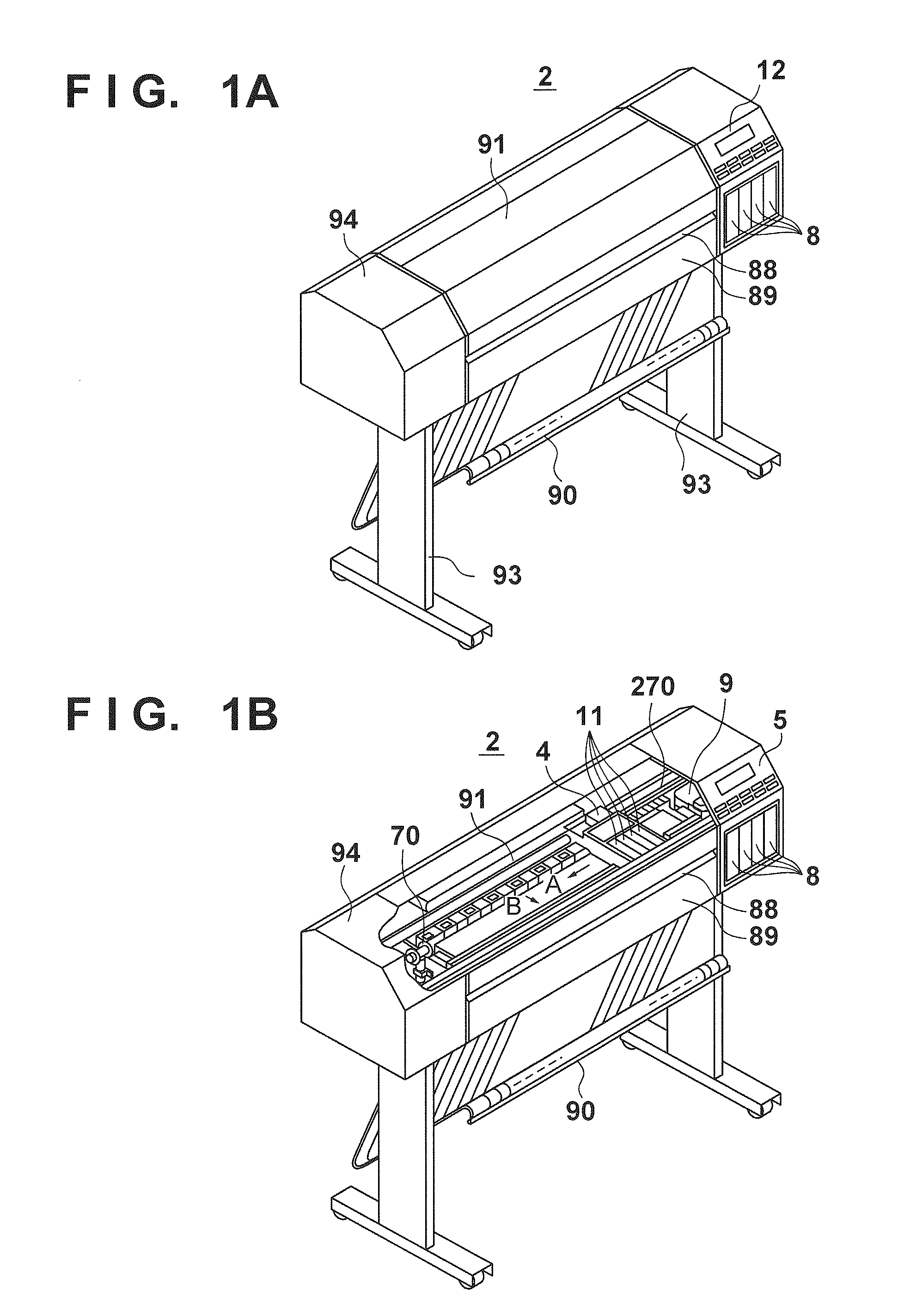
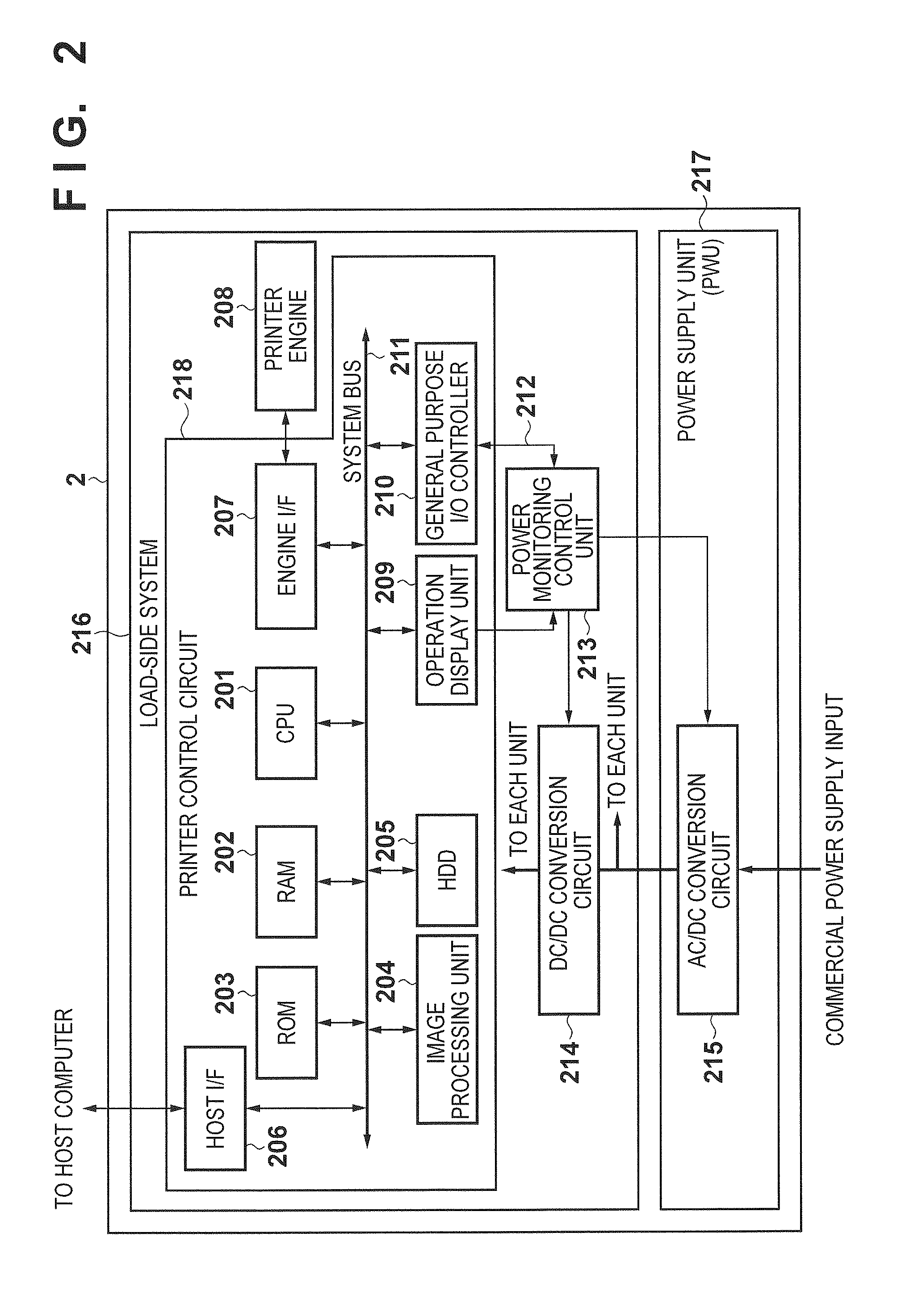
BACKGROUND OF THE INVENTION[0001]1. Field of the Invention[0002]The present invention relates to a printing apparatus and, particularly to a printing apparatus in which a printhead is mounted on a carriage and the printhead prints while reciprocally scanning the carriage.[0003]2. Description of the Related Art[0004]In a printing apparatus configured to allow the user to replace a printhead mounted on a carriage, a poor contact between the electric contact of the printhead and the electric contact of the carriage that occurs when the user replaces the printhead has not completely been solved in practice though electric contacts have been improved.[0005]The poor contact occurs when small dust is sandwiched between the electric contact of the printhead and that of the carriage upon replacing the printhead. Since this problem arises in the apparatus environment, it is difficult to solve this problem regardless of the improvement of the product. As a practical countermeasure to deal with...

Claims


Application Information

Patent Timeline
Patent Type & Authority Patents(United States)
IPC IPC(8): B41J2/175B41J29/38
CPCB41J2/175B41J2/17546B41J2/17526B41J2/1752
Inventor TERAJI, TOMOYA
Owner CANON KK
Learn More