Method of detecting a leak in a hydraulic pitch system

Pending Publication Date: 2022-11-03
SIEMENS GAMESA RENEWABLE ENERGY AS
View PDF0 Cites 0 Cited by
  • Summary
  • Abstract
  • Description
  • Claims
  • Application Information

AI Technical Summary

Benefits of technology

The invention relates to a way to detect leaks in a wind turbine's pitch system. The method is economical and accurate. By monitoring pressure readings in a non-select pitch system, a drop in pressure indicates a leak in a hydraulic cylinder of that system. This allows for quick identification of defective cylinders, avoiding unnecessary downtime. The leak detection arrangement includes an evaluation unit that receives inputs from a functionality test and tracks the progress of pressure readings. The evaluation unit may be software modules running on a processor of a wind turbine control unit. The technical effect of the invention is an efficient and effective solution for identifying leaks in a wind turbine's pitch system.

Problems solved by technology

If a pitch system develops a severe fault that prevents the rotor blade from being correctly pitched, it may be necessary to shut down the wind turbine.
Such a severe fault may be the result of undetected minor fault, for example a gradual deterioration of a seal in a pitch cylinder.
Downtime is expensive and may have a detrimental effect on the annual energy production (AEP) of the wind turbine.
However, it can be difficult to identify a fault and its location in a complex hydraulic circuit such as a rotor blade pitch system.
A hydraulic-related alarm may indicate a problem with a hydraulic pump of a pitch system, an unexpected change in pressure, etc.
Such alarms are quite general, and often do not clearly identify the actual underlying cause.
For these reasons, a leak in a pitch cylinder may go undetected until it develops into a severe fault, which can readily be detected but results in the wind turbine having to be shut down.
Clearly, the costs of such regular inspection procedures would be prohibitive in the case of a wind park with tens or even hundreds of wind turbines.
However, since there may be several faults in a hydraulic system at any one time, and because an alarm may be issued for a reason that is not directly related to the actual fault, it can be difficult to arrive at an informative conclusion from analysis of a hydraulic alarmstack.

Method used


Image

  • Method of detecting a leak in a hydraulic pitch system
  • Method of detecting a leak in a hydraulic pitch system
  • Method of detecting a leak in a hydraulic pitch system

Examples


Embodiment Construction

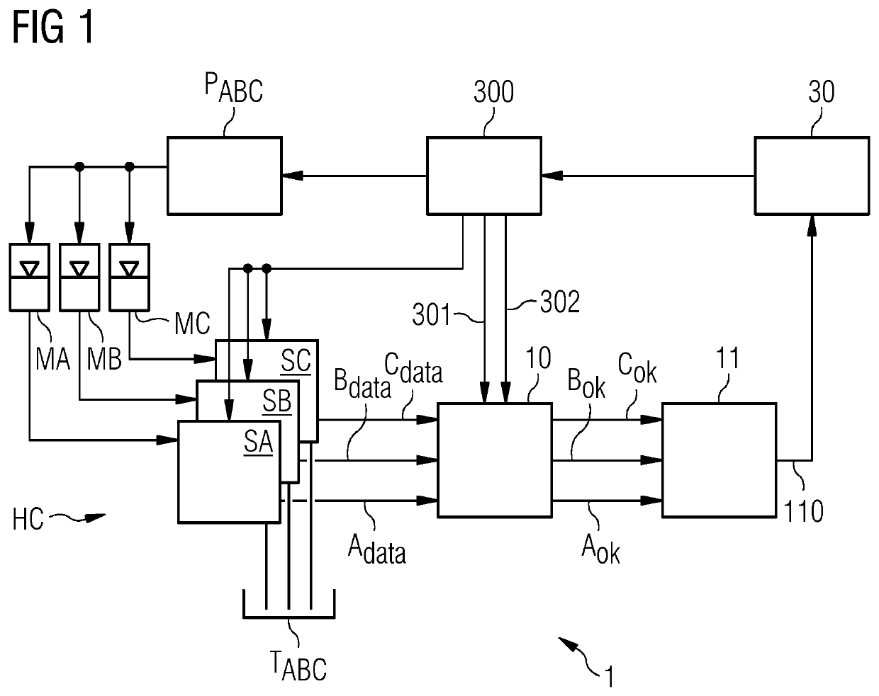
[0041]For a pitch-control wind turbine with three rotor blades, there will be three pitch systems. FIG. 1 shows a simple overview of a hydraulic arrangement of three pitch systems SA, SB, SC of a wind turbine. Each pitch system SA, SB, SC may be assumed to comprise two parallel-connected hydraulic cylinders, as well as an arrangement of valves to regulate the direction of fluid flow. Each pitch system SA, SB, SC is fed from an accumulator MA, MB, MC, and drains into a common tank TABC.

[0042]The accumulators MA, MB, MC and tank TABC may be part of a closed circuit, and all relevant components may be arranged at a convenient location, for example inside the hub of the wind turbine. A scheduler module 300 of the wind turbine (or wind park controller) is used to schedule a functionality test for a selected pitch system, to regulate the hydraulic circuit (by driving the pump PABC and by opening / closing valves of the pitch systems SA, SB, SC accordingly) and to inform an evaluation unit b...


PUM


Abstract

Provided is a method of detecting a leak in a hydraulic cylinder of a rotor blade pitch system of a wind turbine including a plurality of rotor blades, which method includes the steps of selecting one of the pitch systems to undergo a functionality test; actuating a fluid pump to move the pistons of the hydraulic cylinders of the pitch systems to their outermost positions; monitoring the hydraulic cylinder pressure levels of the non-selected pitch systems while performing the functionality test on the selected pitch system; and analyzing the monitored hydraulic cylinder pressure levels of the pitch systems to detect a drop in pressure in a pitch cylinder of a non-selected pitch system. A leak detection arrangement of a pitch-controlled wind turbine; and a pitch-controlled wind turbine are also provided.

Description

CROSS-REFERENCE TO RELATED APPLICATIONS[0001]This application claims priority to PCT Application No. PCT / EP2020 / 061523, having a filing date of Apr. 24, 2020, which is based off of EP Application No. 19175699.8, having a filing date of May 21, 2019, the entire contents both of which are hereby incorporated by reference.FIELD OF TECHNOLOGY[0002]The following relates to a method of detecting a leak in a hydraulic cylinder of a wind turbine rotor blade pitch system, and a leak detection arrangement of a pitch-controlled wind turbine.BACKGROUND[0003]The rotor blade of a wind turbine is generally mounted to the hub by means of a hydraulic pitch system so that the rotor blade can be pitched about its longitudinal axis. In this way, the rotor blade can be pitched into the wind to extract as much energy as possibly from the wind. Equally, the rotor blade can be pitched out of the wind to avoid excessive loading during severe wind conditions.[0004]If a pitch system develops a severe fault th...

Claims


Application Information

Patent Timeline
IPC IPC(8): G01M3/26
CPCG01M3/26F15B19/005F03D17/00F05B2260/79F05B2260/70F05B2270/506F05B2270/301F03D7/0224F05B2270/604Y02E10/72
Inventor CHERRY, AUSTINFORTNER, DENNONANDERSEN, KELD FYHNDALAGER BOLVIG, CARSTENEVANS, KEVINFREDERIKSEN, DAN
Owner SIEMENS GAMESA RENEWABLE ENERGY AS
Why Eureka
Try Eureka